Composite nonlinear optical film, method of producing the same and applications of the same

a nonlinear optical film, composite technology, applied in the field of composite films, can solve the problems of affecting the performance of affecting the performance of the component, and affecting the quality of the liquid crystal material,

Inactive Publication Date: 2001-10-16
REVEO
View PDF31 Cites 16 Cited by
  • Summary
  • Abstract
  • Description
  • Claims
  • Application Information

AI Technical Summary

Problems solved by technology

A drawback of many of these devices, however, is that without further processing, liquid crystal materials tend to be relatively expensive and relatively temperature sensitive.
Also, these materials tend to disadvantageously absorb other materials, which may alter the properties of the component, etc.
Moreover, while polymerized LCs may address some of these drawbacks, such LCs may be undesirable for many applications, due to, for example, inadequate mechanical properties (rigidity) and / or optical properties, (indices of refraction, characteristic wavelengths, etc.).
Moreover, bandwidth has become increasingly pressing requirement of modern communications systems.
However, as billions of dollars are invested in these efforts to expand bandwidth, one significant bottleneck remains--switching node (interconnect) hardware.
This opto-electronic interface introduces latencies and substantially reduces the overall bandwidth of the system.
All-optical (i.e., without opto-electronic conversion) switching technologies utilizing MEMS (microelectromechanical system) or polarization-based technologies preserve the fiber bandwidth but switch slowly, introducing latencies that limit their applicability.
For example, devices using inorganic NLO crystals such as titanium-diffused lithium niobate (Ti:LiNbO.sub.3) tend to have inferior performance due to their weak NLO properties.
In addition, temporal and thermal stability as well as radiation sensitivity are well-known problems.
Furthermore, the inorganic crystal devices are difficult to integrate directly with electronics.
However, these poled polymers have the following disadvantages: small second-order susceptibility, low optical damage threshold, high scattering losses, and limited temperature and temporal stability.
Until these problems are solved, the inherently superior organic NLO crystal materials cannot become useful.
A drawback of this technique is that it tends to be difficult to control the morphology, which is strongly dependent on the NLO material and the film processing.

Method used


Image

  • Composite nonlinear optical film, method of producing the same and applications of the same
  • Composite nonlinear optical film, method of producing the same and applications of the same
  • Composite nonlinear optical film, method of producing the same and applications of the same

Examples


example i

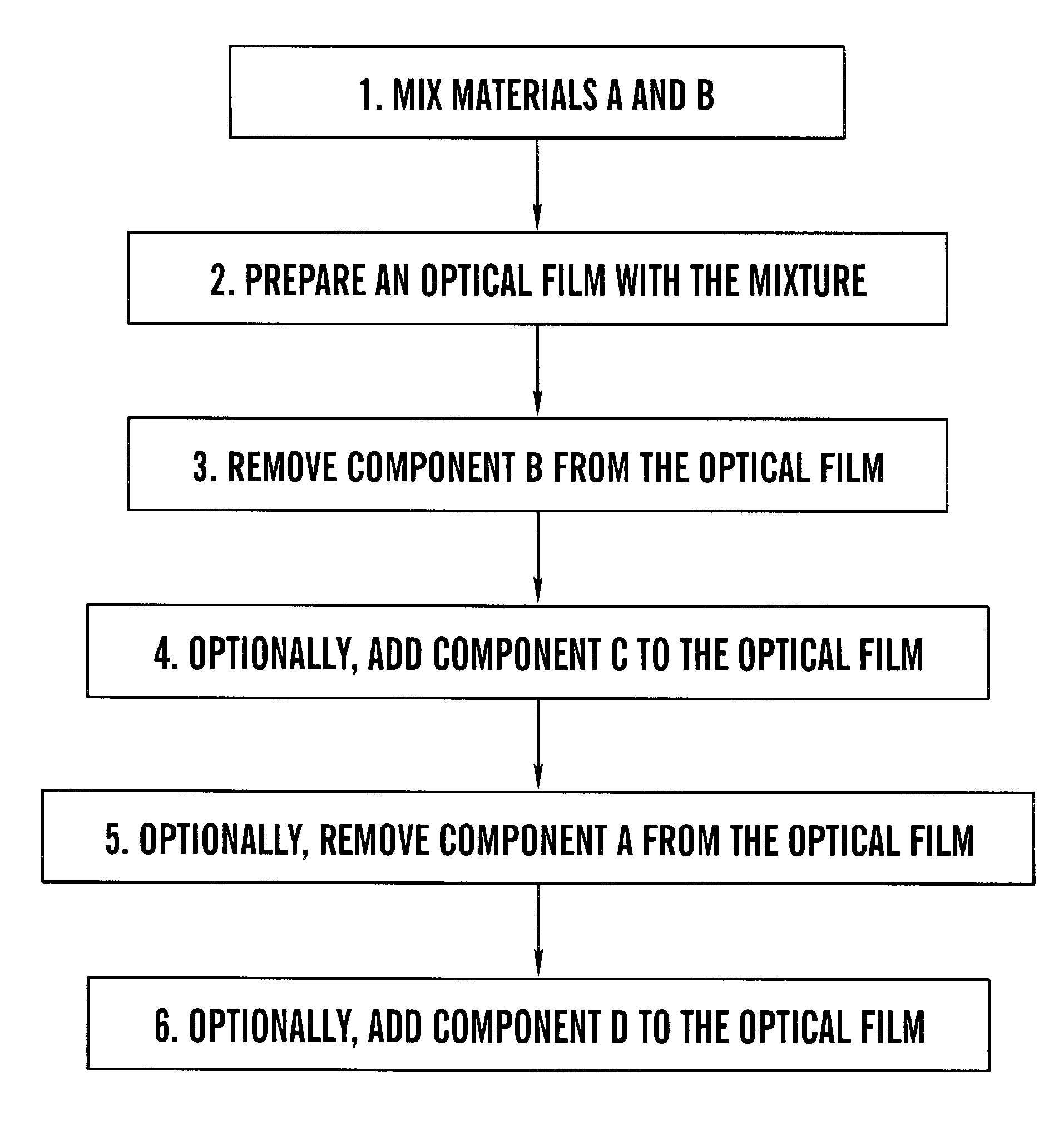
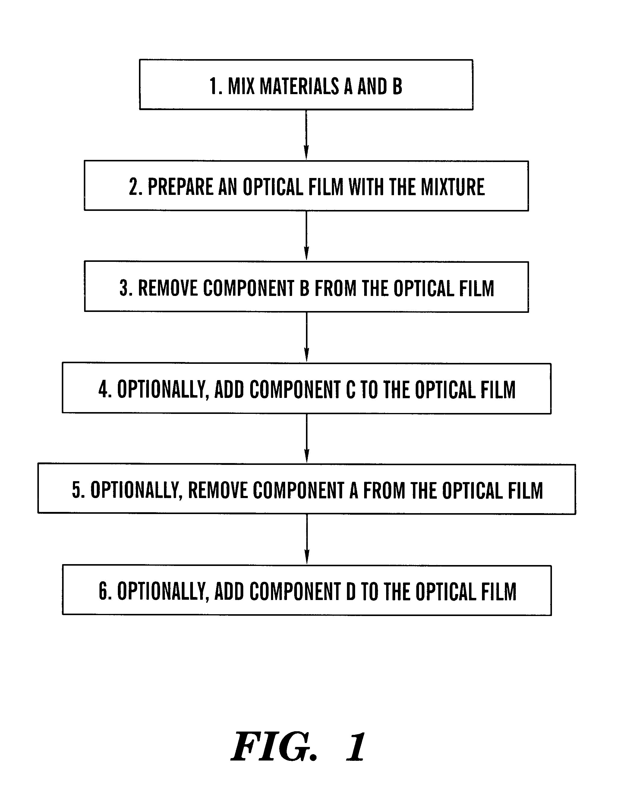
FIG. 4A shows experimental reflectance spectra of film samples that were prepared in accordance of the invented process. Curve 4A1 is the reflectance spectrum of a planar CLC film of a blend consisting of a BASF acrylate CLC polymer #181 (45% by weight), a chiral nematic (53% by weight) and a small amount of Ciba-Geigy photo-initiator Irgacure 184 (2% by weight). The chiral nematic itself consisted of Merck low-molecular-weight nematic liquid crystal E44 and chiral dopant R1011 (0.7% by weight with respect to the chiral nematic). The film was 20 .quadrature.m thick and was prepared in a conventional manner, i.e., two glass substrates were first spin-coated with a thin polyimide alignment layer which are mechanically rubbed. Glass beads of 20 .quadrature.m in diameter were then dispersed between the two glass substrates, with the coated sides facing each other. The CLC blend was then introduced between the substrates by capillary action. After mechanically shearing (relatively small ...

example ii

FIG. 4B shows experimental reflectance spectra of film samples that were prepared in accordance with the invented process. Curve 4B1 was the spectrum of a planar CLC film of the blend consisting of a BASF acrylate CLC polymer #181 (26% by weight), a chiral nematic (69% by weight) and a small amount of Ciba-Geigy photo-initiator Irgacure 184 (5% by weight). The chiral nematic itself consisted of Merck low-molecular-weight nematic liquid crystal E44 and chiral dopant CB15 (24.4% by weight with respect to the chiral nematic). The film was 20 .quadrature.m thick and was prepared in a similar manner described above with respect to Example I. After the film sample was photo-polymerized with a UV lamp and one of the substrates was removed, the reflectance 4A1 was taken from the `naked` film side. In the context of foregoing discussion, A was the BASF 181 polymer, B was the low-molecular chiral nematic. A film with the blend (A+B) was prepared. The B-component (the low-molecular-weight chir...

example iii

FIG. 4C shows experimental reflectance spectra of film samples prepared in accordance with the invented process. Curve 4C1 is the reflectance spectrum of a planar CLC film of the blend consisting of a BASF acrylate CLC polymer #181 (45% by weight), a chiral nematic (53% by weight) and a small amount of Ciba-Geigy photo-initiator Irgacure 184 (2% by weight). The chiral nematic itself consisted of Merck low-molecular-weight nematic liquid crystal E44 and chiral dopant R1011 (0.7% by weight). The film was 20 .mu.m thick and was prepared in a similar manner described above. After the film sample was photo-polymerized with an UV lamp and one of the substrates was removed, the reflectance 4A1 was taken from the `naked` film side. In the context of foregoing discussion, A was the BASF 181 polymer, B was the low-molecular chiral nematic. A film with the blend (A+B) was prepared. The B-component (the low-molecular-weight chiral nematic) was subsequently removed by dissolving with acetone, re...


PUM

PropertyMeasurementUnit
thickaaaaaaaaaa
center wavelengthaaaaaaaaaa
refractive indexaaaaaaaaaa

Abstract

A method is provided for fabricating composite nonlinear optical (NLO) organic films that are suited for use in NLO device applications. The highly NLO properties of these films arise from the vector alignment of "guest' NLO molecules in a self-ordered nano-structured liquid crystal "host' film. Field-poling is used to remove the centro-symmetry. The "guest' concentration is increased by film processing to incorporate oriented nonlinear nano-crystallites to increase nonlinearity. NLO devices based on such films are of low cost and permit fast switching in a compact device format.

Description

BACKGROUND OF INVENTIONThe present invention relates to composite films and more particularly to composite films employing a novel preparation process for nonlinear-optics applications.BACKGROUND INFORMATIONThroughout this application, various publications and patents are referred to by an identifying citation. The disclosures of the publications and patents referenced in this application are hereby incorporated by reference into the present disclosure.Liquid crystals exist in a phase intermediate between a crystalline solid and an isotropic liquid. The molecules of these compounds are usually rod-shaped with long molecular axes called the directors. Liquid crystal phases are characterized by the long-range order (i.e., in the sense of a solid) of the molecules. The nematic phase is the simplest, having only orientational ordering such that their directors are approximately parallel. The cholesteric liquid crystal phase originates from the presence of chirality in the nematic phase....

Claims


Application Information

Patent Timeline
Patent Type & Authority Patents(United States)
IPC IPC(8): C09K19/54G02B1/10G02F1/35G02F1/361G02B5/20B32B7/02G02B5/30G02F1/061G02F1/13G02F1/355H01S3/17
CPCB82Y30/00C09K19/54C09K19/544G02B5/201G02B5/3016G02F1/3558G02F1/361G02F1/3615Y10T428/10G02F2202/02G02F1/061C09K2323/00
Inventor FAN, BUNSENXU, JIANJUN
Owner REVEO
Why Eureka
Try Eureka