Optical filter and method for linearization of optical power equalizer

Inactive Publication Date: 2001-10-23
LUCENT TECH INC
View PDF3 Cites 11 Cited by
  • Summary
  • Abstract
  • Description
  • Claims
  • Application Information

AI Technical Summary

Problems solved by technology

However, these optical amplifiers such, for example, as Erbium-doped fiber amplifiers (EDFA) typically exhibit wavelength dependent gains.
However, it has been found that for overall wavelength ranges of 100 nm, this device still deviated by a

Method used


Image

  • Optical filter and method for linearization of optical power equalizer
  • Optical filter and method for linearization of optical power equalizer
  • Optical filter and method for linearization of optical power equalizer

Examples


Embodiment Construction

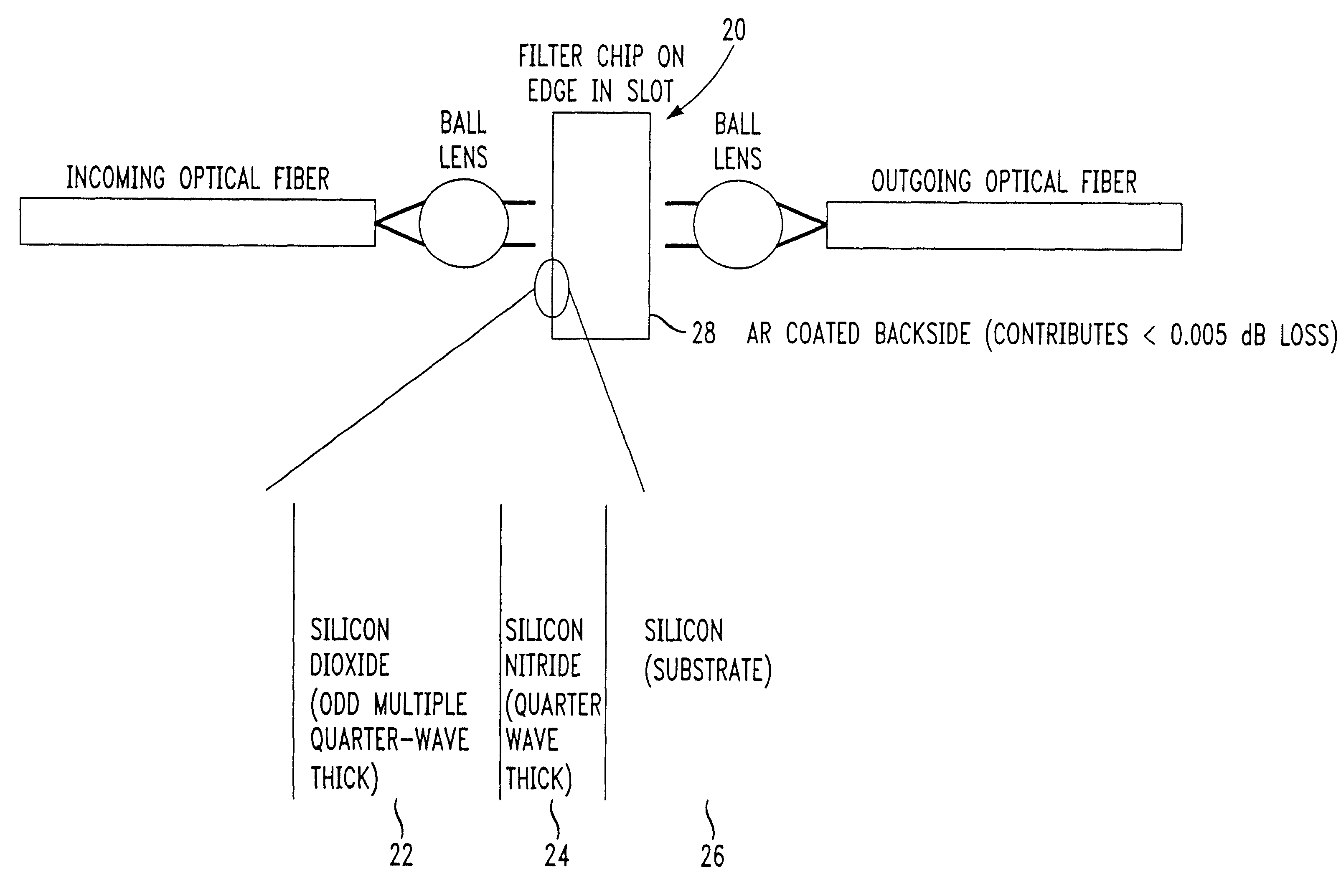
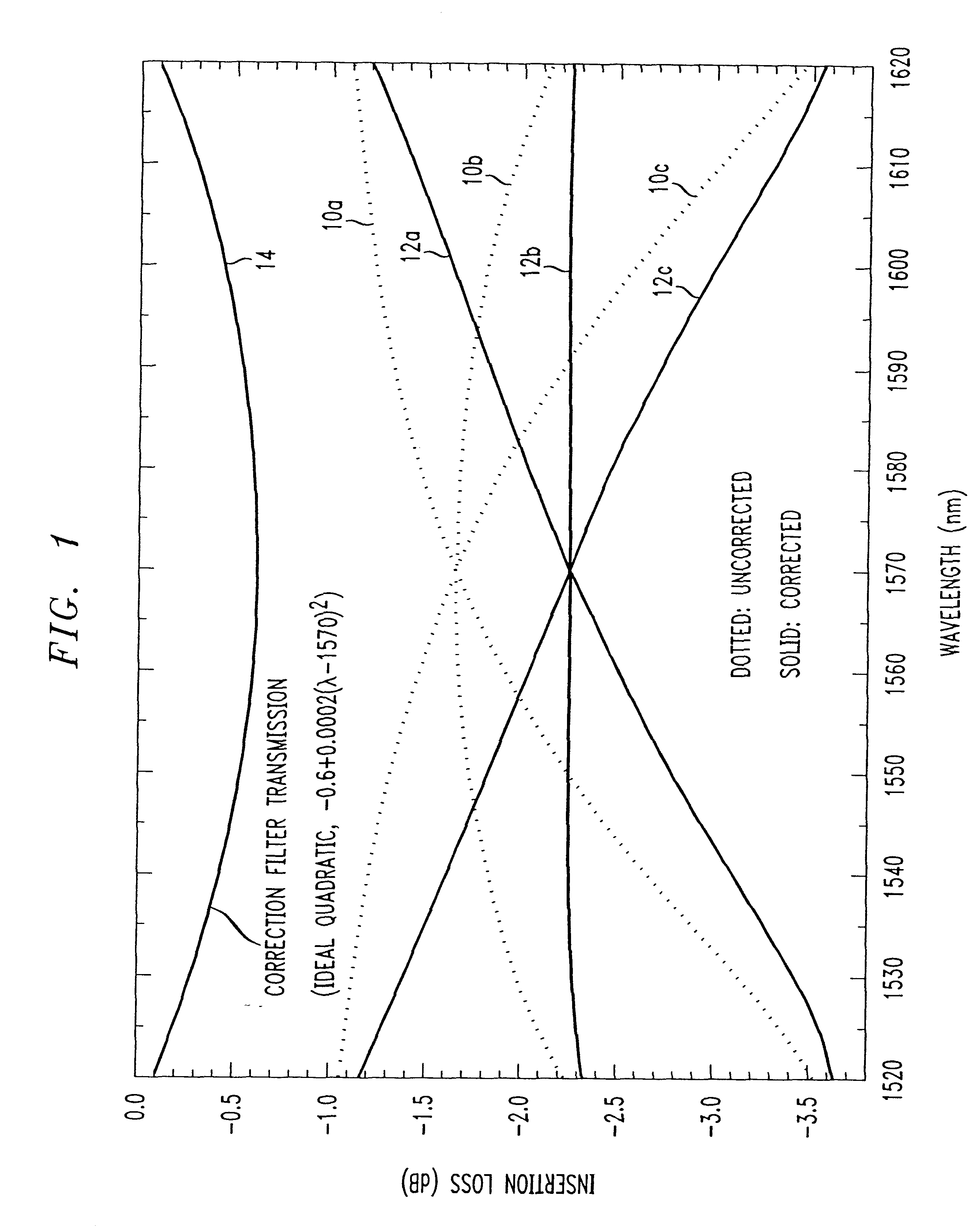
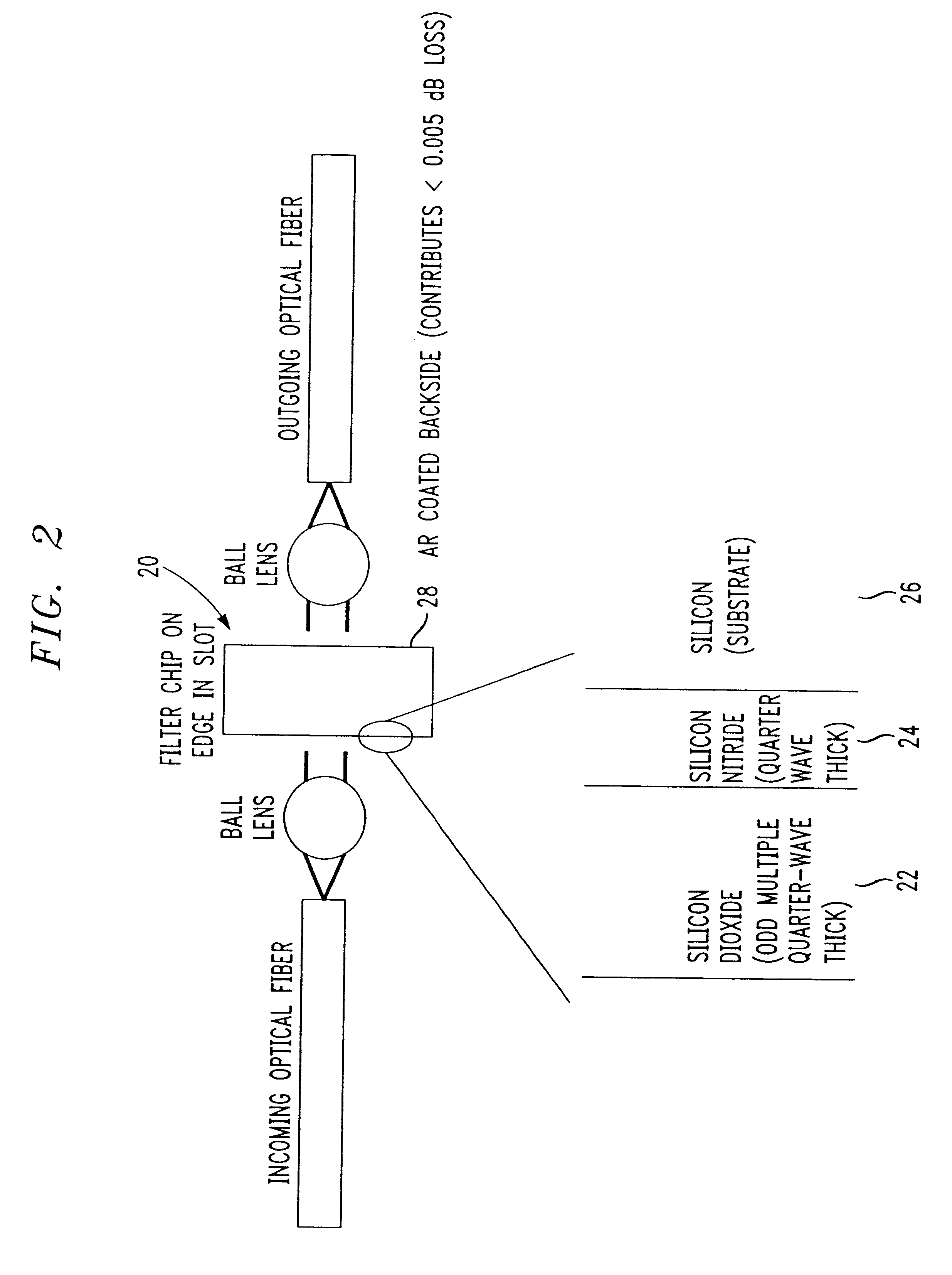
Referring to FIG. 1, an ideal correction filter transmission 14 according to the invention is shown for correcting three outputs 10a, 10b, 10c of an Optical Power Equalizer which is disclosed in commonly-owned and co-pending U.S. patent application Ser. No. 09 / 217,710, filed Dec. 21, 1998, the entire contents of which are expressly incorporated herein by reference. The three separate outputs 10a, 10b, 10c in FIG. 1 represent three different biases of the Optical Power Equalizer. As is readily apparent from FIG. 1, the outputs 10a, 10b, 10c deviate from linearity. It has been discovered that a correction for this deviation from linearity can be approximated by a quadratic shaped curve which results from the quadratic equation:

insertion loss=a+b(.lambda..sub.actual -.lambda..sub.center wavelength).sup.2

where

a=the loss at the center wavelength of a wavelength band to correct linearity;

.lambda..sub.center wavelength =the center wavelength of the wavelength band;

.lambda..sub.actual =the ...


PUM


Abstract

An optical filter for correcting non-linear gains across a wavelength band includes a first layer having a first layer thickness according to the formula: first layer thickness=mlambd/(4nfirst), where m is an odd multiple integer, lambd is the central wavelength of the wavelength band, and nfirst is the refractive index of the first layer, and a second layer having a second layer thickness according to the formula: second layer thickness=lambd/(4nsecond), where lambd is the central wavelength of the wavelength band, and nsecond is the refractive index of the second layer. The optical filter introduces an insertion loss for wavelengths in a wavelength band of optical fiber transmission having an insertion loss curve approximating a quadratic shape in the wavelength band and having a maximum insertion loss at a central wavelength of the wavelength band.

Description

1. Field of the InventionThe present invention relates to an optical filter for correcting non-linear gain or attenuation in a wavelength band of the optical system by adding an insertion loss having a quadratic-shaped insertion loss curve in the wavelength band and having a maximum insertion loss at a center wavelength of the wavelength band.2. Description of the Related ArtOptical fiber communications systems are advantageously and desirably used to transport data in the form of light pulses over long distances because they exhibit a very large capacity for carrying information, are light-weight, and are immune to electromagnetic interference. In some systems, several optical carriers of different wavelengths are used to simultaneously propagate the multiple wavelengths along the same fiber. These are referred to as Wavelength Division Multiplexed (WDM) systems and further increase the capacity of optical systems.In a typical WDM system, optical fiber amplifiers are used to increa...

Claims


Application Information

Patent Timeline
IPC IPC(8): G02B5/28G02B6/34H04B10/18G02B6/32
CPCG02B5/281G02B6/2937G02B6/29391H04B10/25073G02B6/325
Inventor GOOSSEN, KEITH WAYNE
Owner LUCENT TECH INC
Why Eureka
Try Eureka