Plasma processing system with a new inductive antenna and hybrid coupling of electronagnetic power

a processing system and electronagnetic power technology, applied in plasma technology, electric heating, electric/magnetic/electromagnetic heating, etc., can solve the problems of difficult to obtain uniform plasma, difficult to increase the number of turns in the antenna coil, and difficult to achieve uniform plasma

Inactive Publication Date: 2001-10-30
BETHEL MATERIAL RES
View PDF9 Cites 40 Cited by
  • Summary
  • Abstract
  • Description
  • Claims
  • Application Information

AI Technical Summary

Problems solved by technology

Efforts to increase the number of turns in the coil of the antenna have been limited by the self-resonance of the antenna.
`Self-resonance` is an electrical characteristic of the antenna due to the inductive and capacitive effects of the antenna and limits the ability of the antenna to induce an electric field.
Also, obtaining uniform plasma was hard to achieve since the spiral antenna generates a highest electric field at the center of the source and a lower field toward the edge.
However, even with the magnetic field, uniform plasma is hard to obtain.

Method used


Image

  • Plasma processing system with a new inductive antenna and hybrid coupling of electronagnetic power
  • Plasma processing system with a new inductive antenna and hybrid coupling of electronagnetic power
  • Plasma processing system with a new inductive antenna and hybrid coupling of electronagnetic power

Examples


Embodiment Construction

Illustrative embodiments and exemplary applications will now be described with reference to the accompanying drawings to disclose the advantageous teachings of the present invention.

While the present invention is described herein with reference to illustrative embodiments for particular applications, it should be understood that the invention is not limited thereto. Those having ordinary skill in the art and access to the teachings provided herein will recognize additional modifications, applications, and embodiments within the scope thereof and additional fields in which the present invention would be of significant utility.

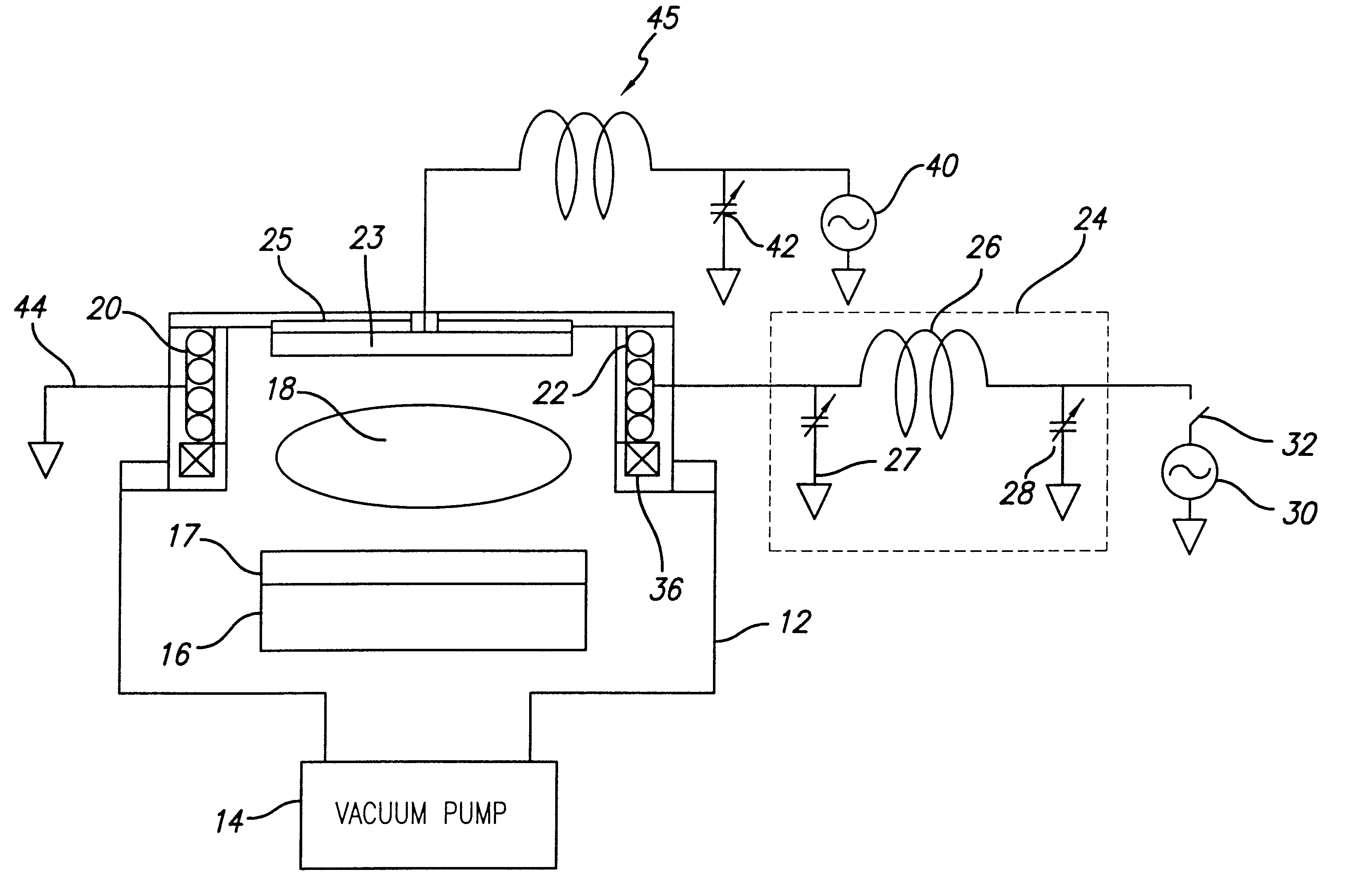
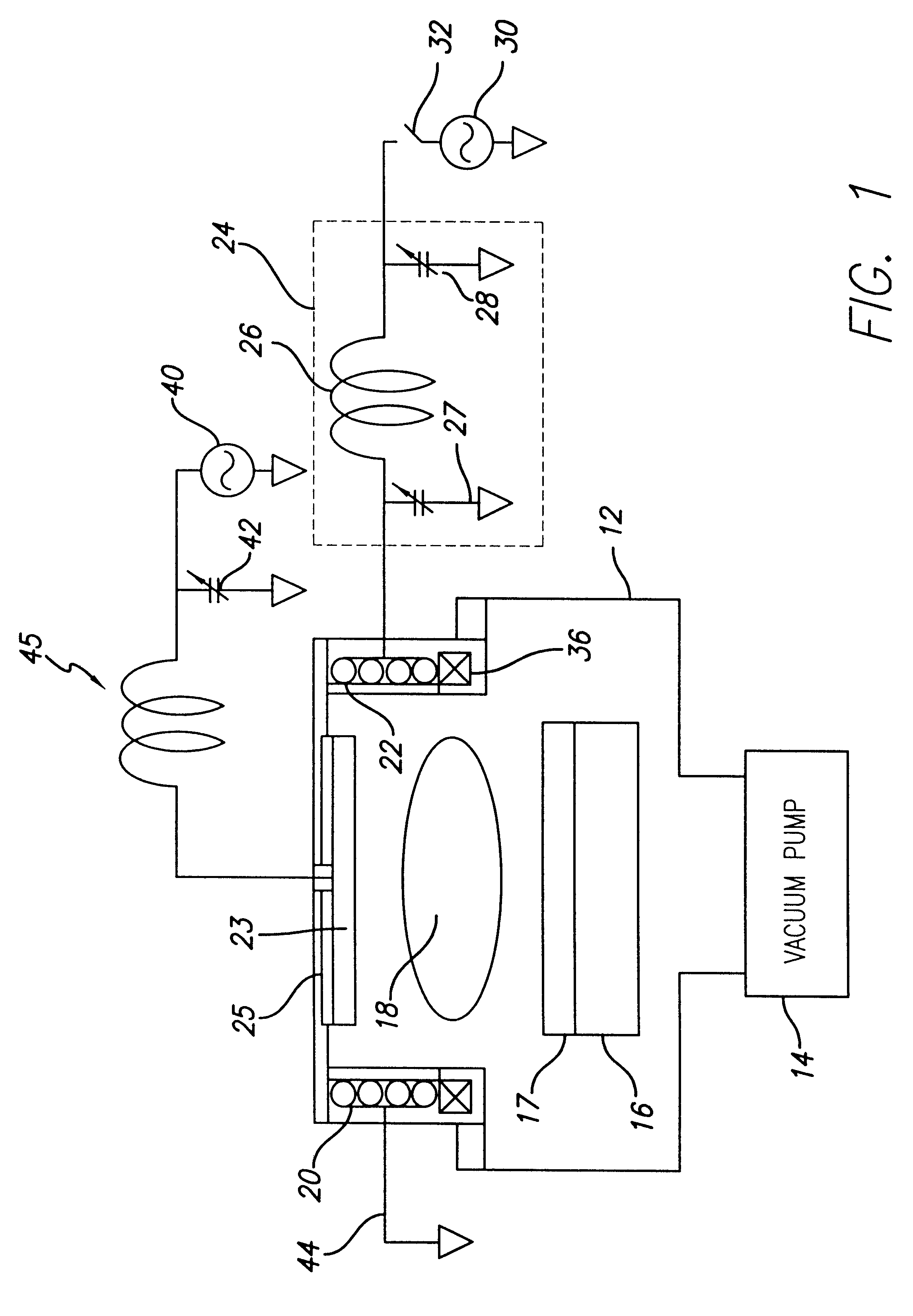
FIG. 1 is a schematic diagram of a plasma processing system incorporating the antenna plasma source of the present invention. The system 10 includes a vacuum chamber 12, which is evacuated by a vacuum pump 14. A substrate holder 16 is shown within the chamber 12 holding a substrate 17. The antenna 20 of the present invention is mounted around a dielectric tube 2...


PUM

PropertyMeasurementUnit
electromagnetic energyaaaaaaaaaa
poweraaaaaaaaaa
impedanceaaaaaaaaaa

Abstract

An antenna adapted to apply a uniform electromagnetic field with high energy density to a volume of gas. The antenna includes an input node for receiving electrical energy and a first coil for radiating electromagnetic energy into the gas. The first coil is connected to the input node on one end thereof and is grounded on the opposite side to cause flux to flow in a first direction. A second coil is included for radiating electromagnetic energy into the gas. The second coil is also connected to the input node on one end thereof and grounded on the opposite side to flow in the first direction. Multiple number of coils can be added to form an antenna. In an illustrative application, the antenna is used in a plasma processing system comprising a vacuum chamber, a gas disposed within the vacuum chamber, and a dielectric disposed around the vacuum chamber. The inventive antenna is mounted around the dielectric tube and radiates electromagnetic energy into the gas. In a specific embodiment, the invention further includes a magnet disposed about the chamber in proximity to the antenna. When RF power is supplied to the antenna via an impedance matching network, the antenna radiates a uniform, dense electromagnetic wave into the gas creating plasma. The invention includes an electrically isolated electrode located on top of the source. When (RF) power is supplied to the electrode via on impedance matching network, the electrode creates an electrostatic force that pushes electrons back into plasma there by resulting in high plasma density.

Description

1. Field of the InventionThe present invention relates to plasma etching systems. More specifically, the present invention relates to plasma sources used for plasma etching, chemical and physical vapor deposition, photo-resist stripping and other applications relating to semiconductor, flat panel display, printed circuit board and other fabrication processes.2. Description of the Related ArtPlasma sources capable of generating uniform plasma over a wide area are needed for plasma etching, plasma enhanced chemical vapor deposition (CVD), physical vapor deposition, photoresist stripping and surface treatments for many applications. Illustrative applications include silicon and compound semiconductor fabrication, flat panel display fabrication including active matrix liquid crystal display, plasma display panels, field emission displays etc. Additional applications include hard disk drive head and media manufacturing, micro-electromechanical system manufacturing and printed wiring boar...

Claims


Application Information

Patent Timeline
Patent Type & Authority Patents(United States)
IPC IPC(8): H01J37/32H05B6/62H05B6/00H05H1/46H05B6/10
CPCH01J37/321H05H1/46
Inventor RA, YUNJU
Owner BETHEL MATERIAL RES
Why Eureka
Try Eureka