Recording apparatus and method

a recording apparatus and a technology of a recording device, applied in the direction of measuring apparatus components, instruments, printing, etc., can solve the problems of large waste, inability to use, and large running costs, and achieve the effect of stabbing ink mists

Inactive Publication Date: 2001-11-13
SONY CORP
View PDF2 Cites 12 Cited by
  • Summary
  • Abstract
  • Description
  • Claims
  • Application Information

AI Technical Summary

Benefits of technology

It should be noted that in addition to the above-mentioned lithography technique used in the semiconductor device manufacturing process, the methods of making the rugged structure may include, for example, embossing, photoetching using a photosensitive resin, wet etching using a photosensitive resin as a mask, electroplating in which electrochemical reaction is applied, etc. Among others, the electroplating can conveniently be used to form the rugged structure without effecting the process of forming the SiO.sub.2 layer, which will take a relatively long time, the process of forming a metal mask and the process of etching the SiO.sub.2 layer. Therefore, the electroplating can effectively be used to form the rugged structure in a considerably shorter time than that required for forming the rugged structure from SiO.sub.2. Thus, the processing time can be reduced to improve the mass productivity and reduce the manufacturing cost.
For an improved storage stability of an image printed on the printing paper by the recording apparatus according to the present invention, the printing paper should desirably have a variety of additives added thereto. Lamination of a protective film such as resin film on the printing paper on which an image or the like is printed will also be effective for a higher storage stability of the printed image.

Problems solved by technology

However, this technique is not advantageous in that the disposable ink sheet will result in a big waste and the running cost is large.
Thus, the technique has not being prevailing.
The conventional thermal transfer type printing provides quality images but the dedicated printing paper and disposable ink ribbon or ink sheet lead to a high running cost.
Because of the principle, however, the ink-jet printing technique can hardly print an image with an intra-pixel density gradation, and thus reproduce in a short time a quality image having a quality as high as that of a silver film image obtainable using the dye diffusion type thermal printing method.
That is, since one droplet of ink forms one pixel, the conventional ink-jet printing technique is hard to print an image with an intra-pixel gradation and cannot form an image having a high quality.
However, this approach cannot assure the same image quality as that in the sublimation thermal printing and the printing speed is considerably lower than that in the sublimation thermal printing.
On the other hand, the satellite droplet method is such that micro droplets of ink generated derivatively just after generation of main droplets of ink are utilized to form an image on the printing material but the main droplets of ink are not used for the image forming.
Generally, it is difficult to microstructure the piezo element.
So, the ultrasonic vibration method is disadvantageous in that no line printer head can be built and thus no high printing speed can be attained.
Also it is difficult to localize the ultrasonic vibration, and thus the microstructuring of the piezo element is further difficult and the cross-talk is a large problem in the ultrasonic vibration method.
This method is actually limited to the so-called continuous ink-jet printing technique and so cannot be implemented with a low cost.
In this method, however, when the printing liquid or ink is heated by the heaters, the ink boiling causes coarse droplets and micro droplets derivatively produced along with main droplets, so-called satellite droplets, which will cause the printing quality to be lower.
Namely, it is difficult to stably jet an ink mist by the surface tension convection.

Method used


Image

  • Recording apparatus and method
  • Recording apparatus and method
  • Recording apparatus and method

Examples


Embodiment Construction

Nonlimitative examples of printing by the recording apparatus according to the present invention will be described below:

Example Nos. 1 and 2 and Comparative Example Nos. 1 and 2

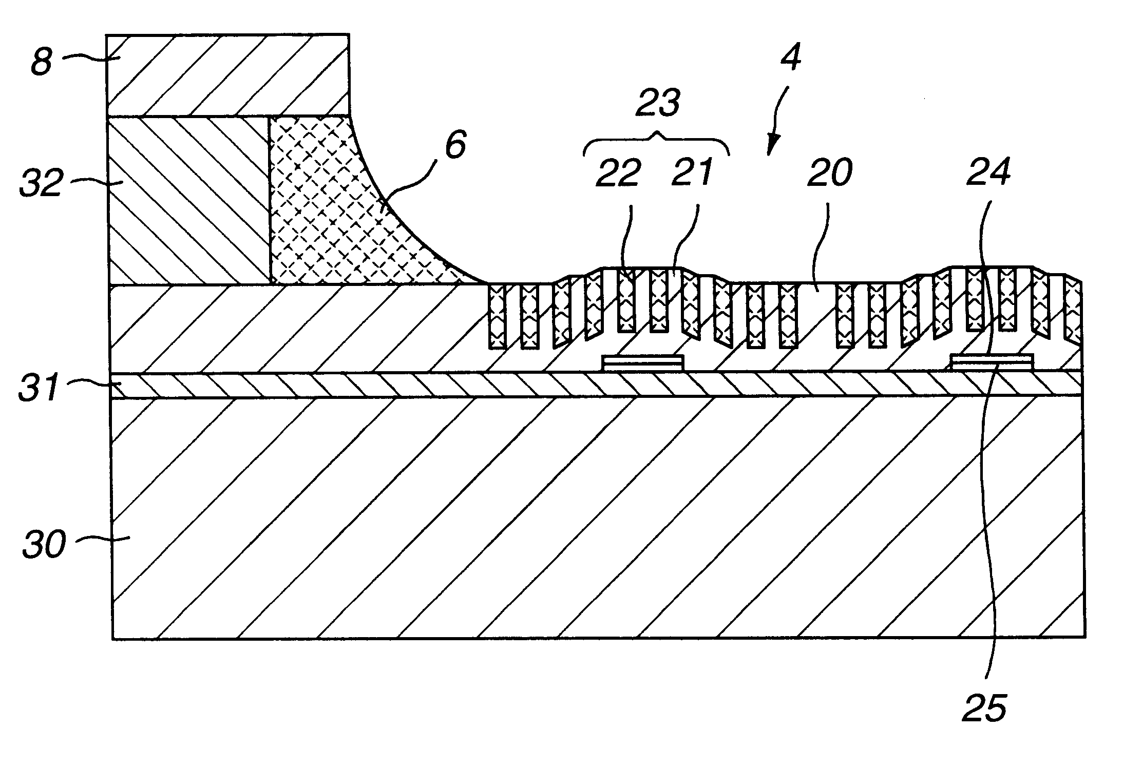
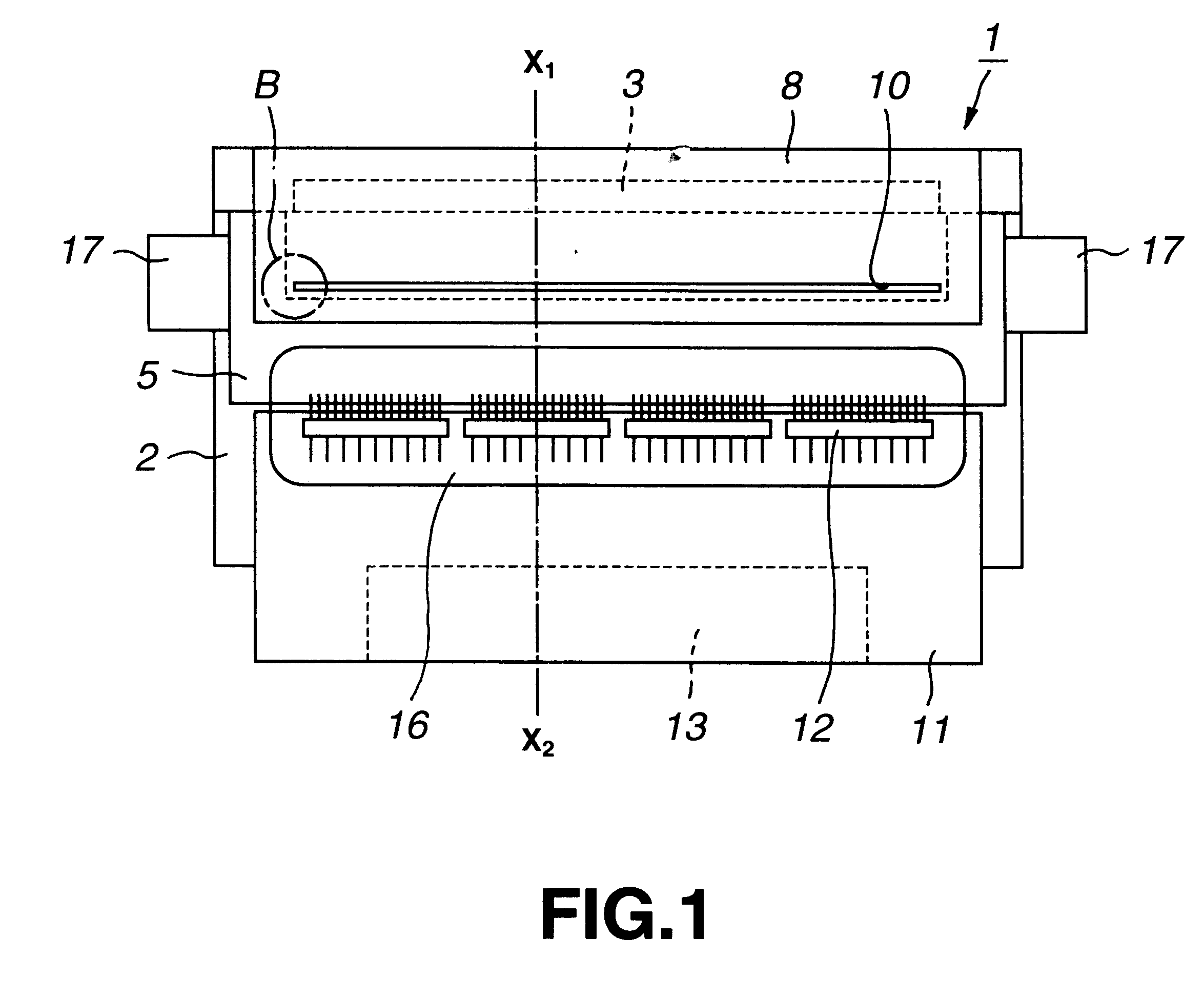
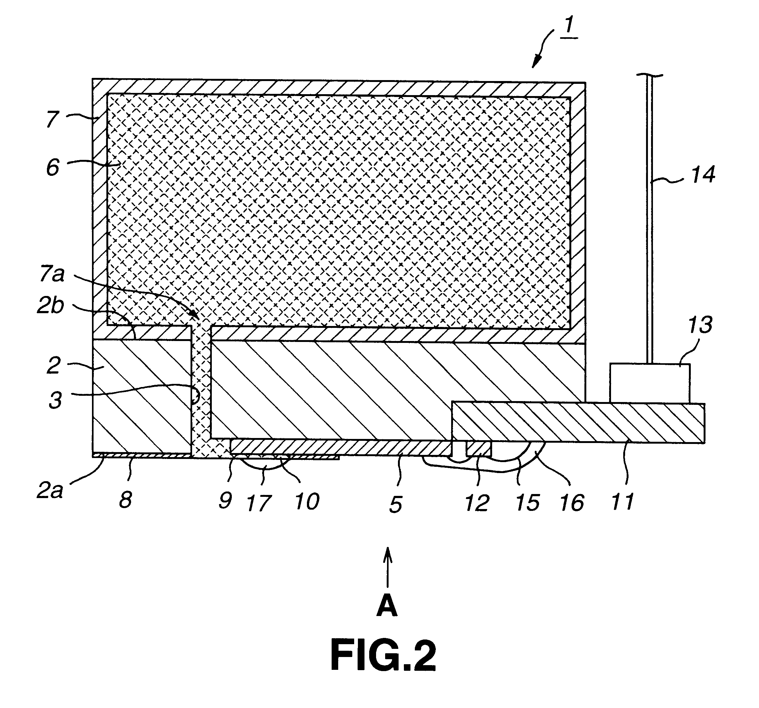
The printer head constructed as shown in FIGS. 1 to 4 is used to print under conditions shown in Table 1. One pixel is formed from 256 voltage pulses given within 4 ms and pixels are continuously printed at a rate of 2 cm / s. Note that in each of the color inks, the dye concentration is 5% by weight.

The properties of SiO.sub.2 forming the projections in the ink transfer block and those of polysilicone forming the heater are shown in Table 2.

In these examples, the projections of SiO.sub.2 formed in the ink transfer block are all 5 m high. The heat conductivity of SiO.sub.2 is one size larger than that of the ink, so that the heat of the heaters provided on the bottoms of the ink transfer blocks is transferred to the ink surface mainly via the projections of SiO.sub.2.

The time taken for the heat to transfer to ...


PUM


Abstract

An ink retained in an ink transfer block is heated by a heating device correspondingly to information to be printed, thereby developing a surface tension gradient and interfacial tension gradient on the ink surface, and a fluidity caused by the surface tension gradient and / or interfacial tension gradient of the ink surface is utilized to have the ink fly from the ink transfer block, thereby printing the information on a print receptor, the heating device having a heating velocity v (in K / s) which meets a requirement (Tb-Ti) / v>h2 / D where Tb is a boiling point of the ink in K; Ti is an initial temperature of the ink in K; h is the shortest distance between the surface of the heating means and ink surface in m; and D is a coefficient of thermal diffusion in m2 / s.

Description

1. Field of the InventionThe present invention relates to a thermal transfer type recording apparatus and method, capable of recording an image in a continuous gradation.2. Description of the Related ArtAlong with the recent advanced technology of recording in colors data from the video camera, computer graphic data, etc., the demands for recording in a single color as well as for hard copying in colors have become greater. To accommodate such demands, color hard copying techniques such as the sublimation type thermal printing, fusion type thermal printing, ink-jet printing, electrophotographic printing, heat development type silver film image printing, etc. have been proposed. Among these printing techniques, the dye diffusion thermal printing technique (sublimation type thermal printing) and ink-jet printing technique can be implemented by a simple apparatus to easily provide quality images.Of these recording techniques, the dye fusion thermal printing technique is such that an in...

Claims


Application Information

Patent Timeline
Patent Type & Authority Patents(United States)
IPC IPC(8): B41J2/005B41J2/215B41J2/015
CPCB41J2/005
Inventor SHINOZAKI, KENJI
Owner SONY CORP
Why Eureka
Try Eureka