
Closed drift hollow cathode

a hollow cathode and closed-drift technology, which is applied in the manufacture of electrode systems, electric discharge tubes/lamps, magnetic discharge control, etc., can solve the problems of localized thermal damage, poor utilization of emissive materials in inserts, and the practical limit of the diameter increase that can be used, so as to avoid excessive and damaging increases in electron emission

Inactive Publication Date: 2001-11-27
KAUFMAN & ROBINSON
View PDF6 Cites 9 Cited by
  • Summary
  • Abstract
  • Description
  • Claims
  • Application Information

AI Technical Summary

Benefits of technology

In light of the foregoing, it is an overall general object of the invention to provide an improved hollow cathode that is simple, compact, and reliable.
A further object of the present invention is to provide an improved hollow cathode that better utilizes the available emitting surface, rather than permitting most of the emission to come from only a small portion of that surface.
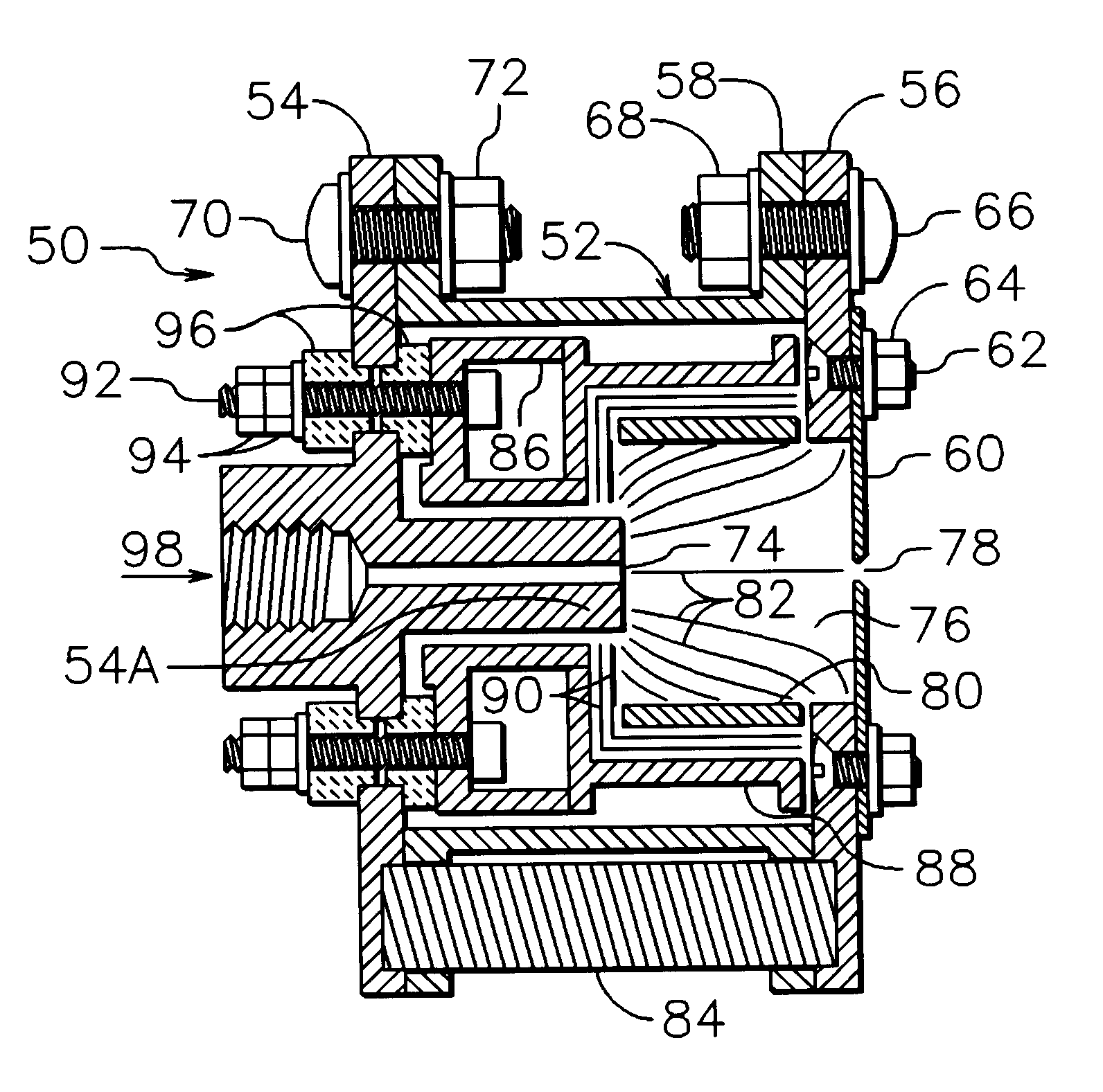
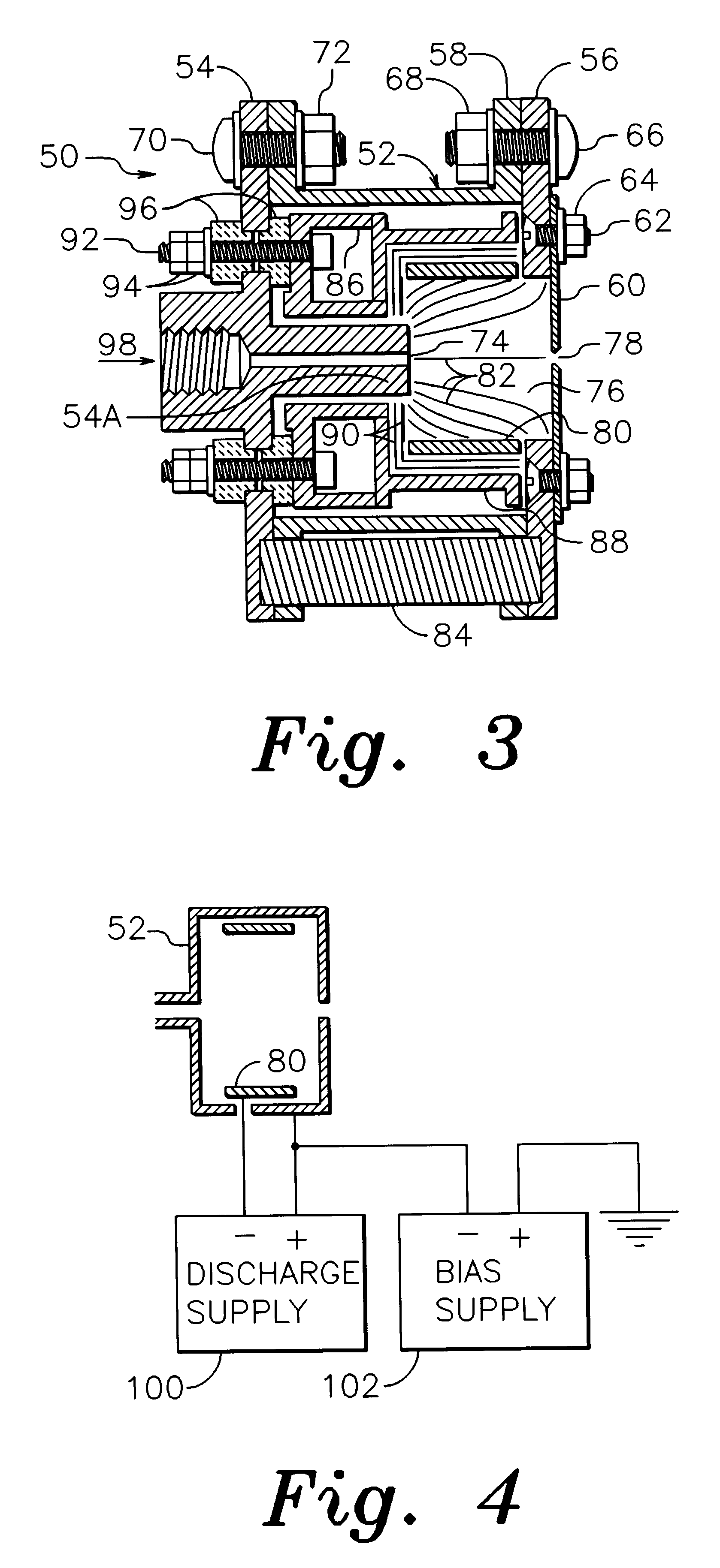
In accordance with one specific embodiment of the present invention, the closed drift hollow cathode comprises an axisymmetric discharge region into which an ionizable gas is introduced, an annular electron emitting cathode insert disposed laterally about that discharge region, a surrounding enclosure, an aperture in said enclosure disposed near the axis of symmetry and at one end of said region, and a magnetic field within said region which is both axisymmetric and generally disposed transverse to a path from said cathode insert to said aperture. The cathode insert is biased negatively relative to the surrounding enclosure, establishing both an electrical discharge and a discharge plasma in the discharge region. The electrons emitted from the cathode insert drift in closed paths around the axis, collide with molecules of ionizable gas, and sustain the discharge plasma by generating additional electron-ion pairs. Ions from the plasma bombard the cathode insert, thereby maintaining an emissive temperature. Electrons from the plasma diffuse to and escape through the aperture to provide the electron emission. Ions also escape through the aperture to charge neutralize the electrons. The closed drift nature of the discharge circumferentially distributes the heating of the cathode insert and the utilization of the electron emitting capabilities thereof. The discharge current between the cathode insert and the enclosure establishes a maximum value on the electron emission, approximately equal to the discharge current, thereby avoiding excessive and damaging increases in electron emission during electrical breakdowns of related equipment.

Problems solved by technology

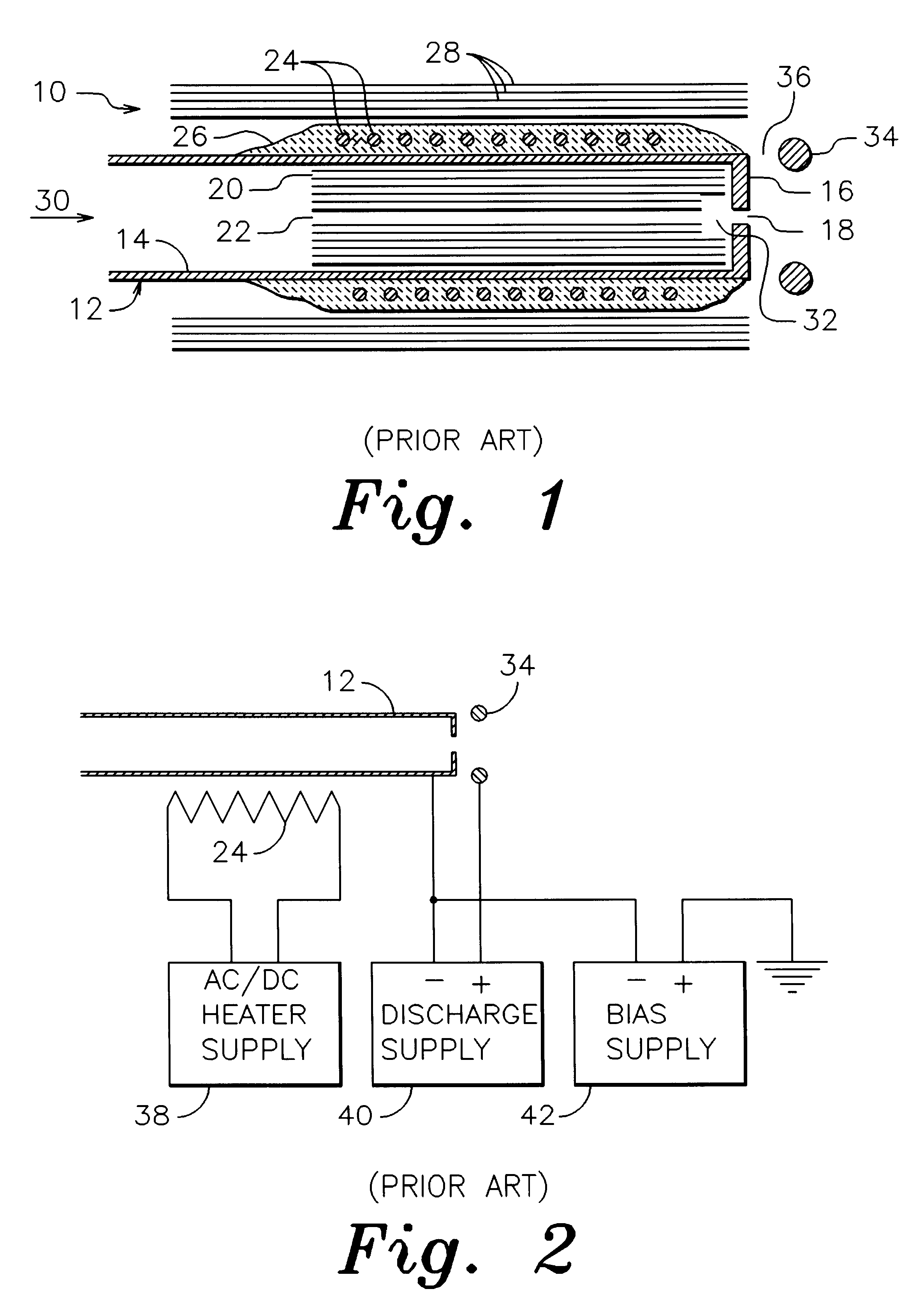
This localized heating can result in poor utilization of the emissive material in the insert or, in extreme cases, localized thermal damage.
There is a practical limit to the increase in diameter that can be used, however, because of the tendency of low density discharges to concentrate on one localized cathode area, even if a larger area is equally accessible.
These devices can have electrical breakdowns.
The voltages of various electrodes in these devices can fluctuate rapidly during electrical breakdowns, resulting in corresponding variations in electron emission that can cause damage to the devices.
It is typical of these breakdowns that the currents rise extremely rapidly, so that fast acting electronic controls are required to limit these currents.

Method used


Image

  • Closed drift hollow cathode
  • Closed drift hollow cathode
  • Closed drift hollow cathode

Examples


specific example

As a specific example of operation, a configuration similar to that shown in FIG. 7 was used with an electrical circuit similar to that shown in FIG. 4. The aperture plate 60 was made of tantalum and pole pieces 54 and 56 were made of low carbon steel. Outer shell 58 and structural members 110 and 112 were made of nonmagnetic stainless steel. The drawing in FIG. 7 is approximately to scale. There were eight alnico 5 magnets distributed uniformly around the circumference and the aperture 78 had a diameter of 1.5 mm. With an argon gas flow of 7 sccm (standard cubic centimeters per minute) and a 2 ampere, 38 volt discharge, the emission was 1.0 ampere at a bias voltage of 50 volts. A metallic plate was used to collect the electron emission. The bias voltage may appear high, but it is normal for the bias voltage to be higher when the electron conduction is to a metallic electrode instead of a plasma. Erosion measurements of the cathode insert indicated an expected lifetime of hundreds o...


PUM


Abstract

In accordance with one specific embodiment of the present invention, the closed drift hollow cathode comprises an axisymmetric discharge region into which an ionizable gas is introduced, an annular electron emitting cathode insert disposed laterally about that discharge region, a surrounding enclosure, an aperture in that enclosure disposed near the axis of symmetry and at one end of that region, and a magnetic field within that region which is both axisymmetric and generally disposed transverse to a path from the cathode insert to the aperture. An electrical discharge is established between the cathode insert and the enclosure. The electrons emitted from the cathode insert drift in closed paths around the axis, collide with molecules of ionizable gas, and sustain the discharge plasma by generating additional electron-ion pairs. Ions from the plasma bombard the cathode insert, thereby maintaining an emissive temperature. Electrons from the plasma diffuse to and escape through the aperture to provide the electron emission. The closed drift nature of the discharge circumferentially distributes the heating of the cathode insert and the utilization of the electron emitting capabilities thereof. The discharge current controls the maximum value of the electron emission.

Description

This invention relates generally to electron emitting cathodes, and more particularly to hollow cathodes that utilize a flow of ionizable gas.This invention can find application in a variety of devices that employ electron emitting cathodes in electrical discharges, such as ion thrusters used in space propulsion and ion sources used in industrial applications.Electron emitting cathodes are used in a variety of low pressure plasma devices, where low pressure is defined as extending downward from a maximum of about 10 millitorr (1.3 Pascal). They are used in gridded ion sources, as described in an article by Kaufman, et al., in the AIAA Journal, Vol. 20 (1982), beginning on page 745. They are also used in gridless ion sources, as described in U.S. Pat. No. 4,862,032--Kaufman, et al. Ion thrusters also use electron emitting cathodes, as described in U.S. No. Pat. 5,359,254--Arkhipov, et al. Ion thrusters are generally similar to industrial ion sources, except that they are used for spa...

Claims


Application Information

Patent Timeline
Patent Type & Authority Patents(United States)
IPC IPC(8): F03H1/00H01J3/02H01J1/02H01J3/00H01J1/00H01J1/50
CPCF03H1/00H01J1/025H01J1/50H01J3/025
Inventor ZHURIN, VIACHESLAV V.KAHN, JAMES R.KAUFMAN, HAROLD R.
Owner KAUFMAN & ROBINSON
Learn More