Exhaust gas emission control apparatus of hybrid vehicle

a technology of exhaust gas and control apparatus, which is applied in the direction of hybrid vehicles, electrical control, machines/engines, etc., can solve the problems of difficult to sufficiently lessen the harmful gas components present in exhaust gas, unstable combustion in the engine, and relatively large amounts of unburned fuel left untreated,

Inactive Publication Date: 2001-12-11
TOYOTA JIDOSHA KK
View PDF12 Cites 111 Cited by
  • Summary
  • Abstract
  • Description
  • Claims
  • Application Information

AI Technical Summary

Benefits of technology

The adsorbent is heated mainly by heat transferred from exhaust gas. Therefore, it is possible to delay an increase of the temperature of the adsorbent by decreasing the temperature of exhaust gas flowing through the adsorbent and by decreasing a rate of flow of exhaust gas through the adsorbent. To decrease the exhaust gas temperature and the exhaust gas flow, the load on the engine may be decreased by decreasing the drive power output from the engine. A mere decrease of the drive power outputted from the engine may result in insufficient vehicle driving force and may consequently result in a deterioration of drivability. Therefore, it is preferable that the power output from the electric motor be increased simultaneously with a decrease in the power from the engine to secure a desired vehicle driving force.

Problems solved by technology

That is, when the temperature of such a catalyst is below its activation temperature (e.g, at the time of cold start of the engine, or the like), it is difficult to sufficiently lessen harmful gas components present in exhaust gas.
However at this time, combustion in the engine becomes unstable.
If the exhaust gas emission catalysts are not activated in this situation, relatively large amounts of unburned fuel are left untreated and are emitted into the atmosphere.
As a result, the temperature in the filter chamber rapidly rises, so that unburned fuel adsorbed in the filter chamber starts to desorb.
In that case, therefore, the adsorbing capability of the filter chamber is not fully utilized.
Furthermore, if the filter chamber temperature rapidly increases due to an increase in the engine load, the filter chamber temperature reaches the predetermined temperature before activation of the catalytic converter, so that unburned fuel released from the filter chamber may be let out into the atmosphere without being sufficiently treated.
A mere decrease of the drive power outputted from the engine may result in insufficient vehicle driving force and may consequently result in a deterioration of drivability.

Method used


Image

  • Exhaust gas emission control apparatus of hybrid vehicle
  • Exhaust gas emission control apparatus of hybrid vehicle
  • Exhaust gas emission control apparatus of hybrid vehicle

Examples


Embodiment Construction

A preferred embodiment of the hybrid vehicle exhaust gas emission control apparatus of the invention will be described in detail hereinafter with reference to the accompanying drawings.

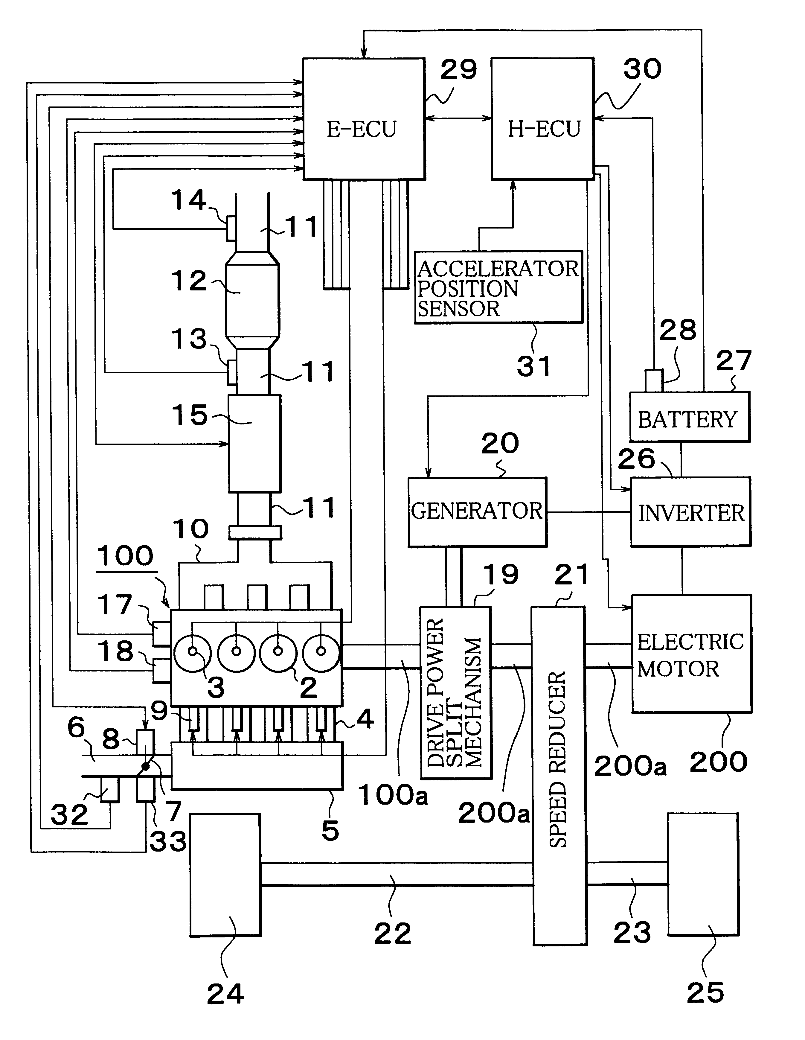
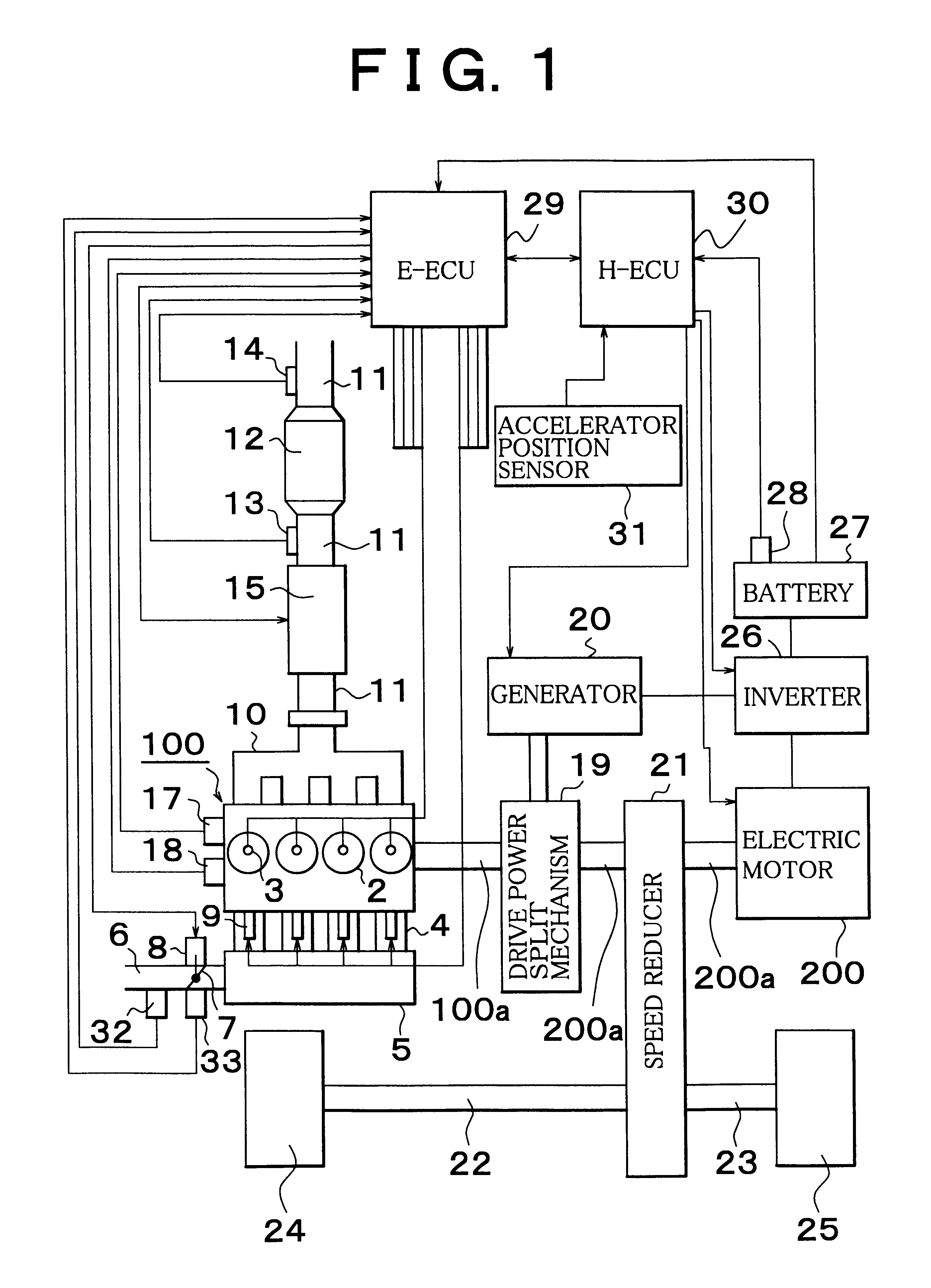
FIG. 1 is a schematic illustration of a hybrid mechanism of a hybrid vehicle to which the exhaust gas emission control apparatus of the invention is applied. The hybrid mechanism incorporates two drive power sources, that is, an internal combustion engine 100 and an electric motor 200.

The engine 100 is a four-cylinder four-stroke gasoline engine. In the engine 100, each cylinder 2 is provided with an ignition plug 3 in such a manner that the ignition plug 3 faces a combustion chamber (not shown) of the cylinder. The engine 100 is equipped with a crank position sensor 17 that outputs a pulse signal every time a crankshaft 100a of the engine 100, that is, an engine output shaft, rotates a predetermined angle (e.g., 30.degree.), and a water temperature sensor 18 that outputs an electric signal correspond...


PUM


Abstract

An exhaust gas emission control apparatus is provided in an exhaust passage of a hybrid mechanism driven by an internal combustion engine and an electric motor. The apparatus has an adsorbent that adsorbs unburned fuel contained in exhaust gas when the temperature of the adsorbent is lower than a predetermined temperature, and that releases adsorbed unburned fuel therefrom when the temperature is at least the predetermined temperature. When the temperature of the adsorbent is lower than the predetermined temperature, the apparatus controls the hybrid mechanism to delay an increase in the temperature of the adsorbent.

Description

1. Field of the InventionThe present invention relates to an exhaust gas emission technology for a hybrid vehicle driven by an internal combustion engine and an auxiliary power source.2. Description of the Related ArtRecently, there has been a demand for a reduction in fuel consumption of and emissions from internal combustion engines installed in motor vehicles. As a consequence, hybrid vehicles having two drive power sources, e.g., an internal combustion engine and an electric motor, have been pursued.Known hybrid vehicles have incorporated an internal combustion engine, an electric power generator that is operated by drive power from the engine, a battery for storing electric power generated by the generator, an electric motor operated by electric power generated by the generator and / or electric power stored in the battery, wheels connected mechanically to a rotating shaft of the electric motor, and a drive power split mechanism that distributes drive power from the engine to the...

Claims


Application Information

Patent Timeline
Patent Type & Authority Patents(United States)
IPC IPC(8): B60K6/00B60K6/04F01N3/08F02D41/02B60W10/06B60K17/04B60W10/08B60W10/26B60W20/00F01N3/20F01N3/24F02D29/02F02D45/00
CPCB60K6/445B60W10/06B60W10/08B60W10/26B60W20/00F01N3/0814F01N3/0878F02D41/0235B60L2240/445B60W2510/068B60W2710/0666F01N2570/12F01N2570/14F02D2200/0802F02D2250/18Y02T10/54Y02T10/6286Y02T10/6239Y02T10/40Y02T10/62B60W20/15
Inventor HIROSE, KATSUHIKO
Owner TOYOTA JIDOSHA KK
Why Eureka
Try Eureka