Method and apparatus for producing nitrogen from air by cryogenic distillation

a technology of cryogenic distillation and air, which is applied in the direction of lighting and heating apparatus, refrigeration and liquid storage, solidification, etc., can solve the problem that simple two-column systems do not necessarily have lower unit energy requirements, and achieve high nitrogen recovery, low unit energy consumption, and high nitrogen recovery

Inactive Publication Date: 2001-12-18
AIR WATER GAS SOLUTIONS INC
View PDF9 Cites 10 Cited by
  • Summary
  • Abstract
  • Description
  • Claims
  • Application Information

AI Technical Summary

Benefits of technology

An object of the invention is to provide a process for a two-column cryogenic distillation of air which achieves high nitrogen recovery, low unit energy consumption, and, though nitrogen is produced by each distillation column operating at different pressures, the product gaseous nitrogen is delivered at a single pressure, a desirable and convenient feature, while maintaining high nitrogen recovery and low unit energy consumption.
It can be seen then that such a system described above becomes easier to effect as the pressure difference between the high pressure column and the reduced pressure derived from the bottoms product from the low pressure column becomes greater. This pressure difference, or some function of this pressure difference, when coupled with the quantity of nitrogen actually recovered, has a direct impact on the requisite energy to produce a nitrogen product. A greater pressure difference indicates a higher energy consumption.
The current invention improves on this process by conducting the condensation of vapors at the pressure of the high pressure column, all of which may be the overhead vapor from the high pressure column, in at least two stages of coolant vaporization in series. The composition of the boiling stream becomes richer in oxygen as the extent of vaporization increases. At essentially a constant temperature of vaporization, the first stage of vaporization occurs at a higher pressure and the second stage at a lower pressure. The vapor from the first stage is both richer in nitrogen and higher in pressure than the vapor from the second stage, and constitutes a feed to the low pressure column. Therefore, the pressure of the low pressure column is maximized--a desirable effect for a given high pressure column pressure, and oxygen is preferentially rejected from the column system from the second stage condenser. Because the composition of the liquid bottoms from the low pressure column are related to the composition of the vapor feed to the bottom of the low pressure column, these bottoms are richer in nitrogen and vaporize at a colder temperature when transferred to the low pressure column condenser and reduced in pressure, allowing the low pressure and high pressure columns to operate at pressures closer together. The low pressure column condenser typically operates just above atmospheric pressure. The effects of reducing head pressure and rejecting an oxygen-rich mixture from the second or last stage of the high pressure column condenser lead to lower compression energy and higher nitrogen recovery, which minimize unit energy expenditure for the nitrogen produced.
The vaporized rich liquid from separator 16 is fed to the bottom of the low pressure column 20. This rich liquid vapor was vaporized at essentially the operating pressure of the low pressure column. The balance of the rich liquid which was passed to condenser 18 is vaporized, is partially warmed in subcooler 19 and main heat exchanger 11 and turboexpanded in 12 to produce refrigeration. The turboexpander exhaust gas 109 is warmed in subcooler 19 and main heat exchanger 11 and may be used elsewhere or vented to atmosphere. This is a stream of elevated oxygen content; and therefore, its disposition in this manner assists in the separation of the air to make the nitrogen product.

Problems solved by technology

Nevertheless, simple two-column systems do not necessarily have lower unit energy requirements than improved single column systems.

Method used


Image

  • Method and apparatus for producing nitrogen from air by cryogenic distillation
  • Method and apparatus for producing nitrogen from air by cryogenic distillation
  • Method and apparatus for producing nitrogen from air by cryogenic distillation

Examples


Embodiment Construction

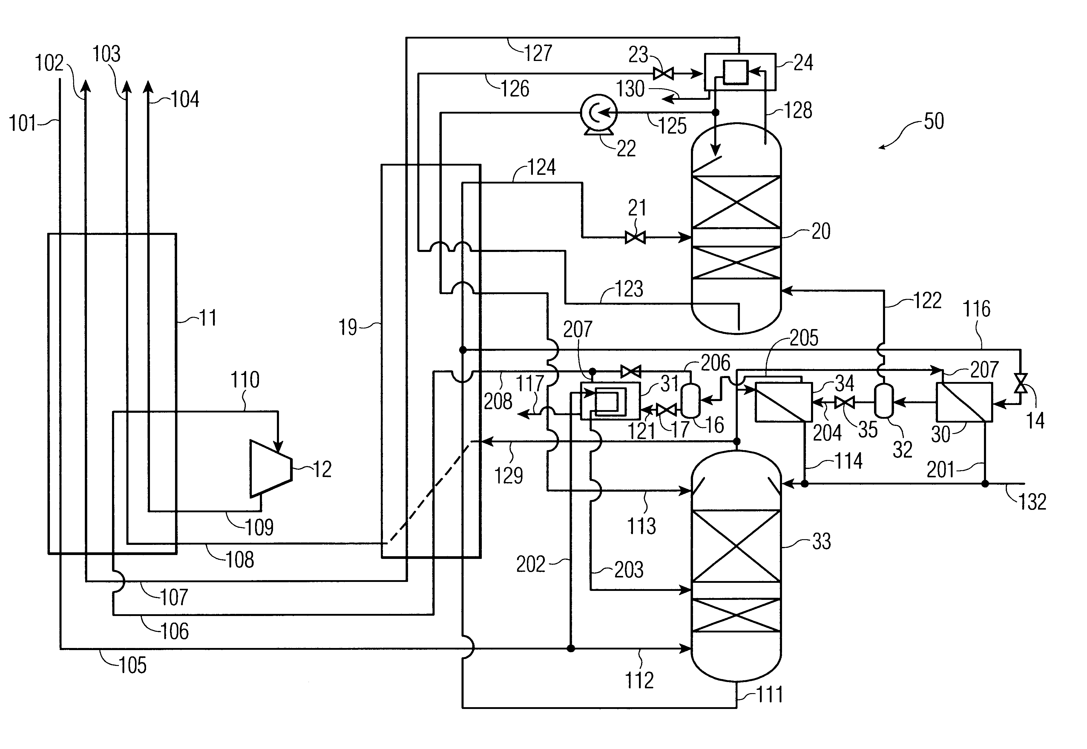
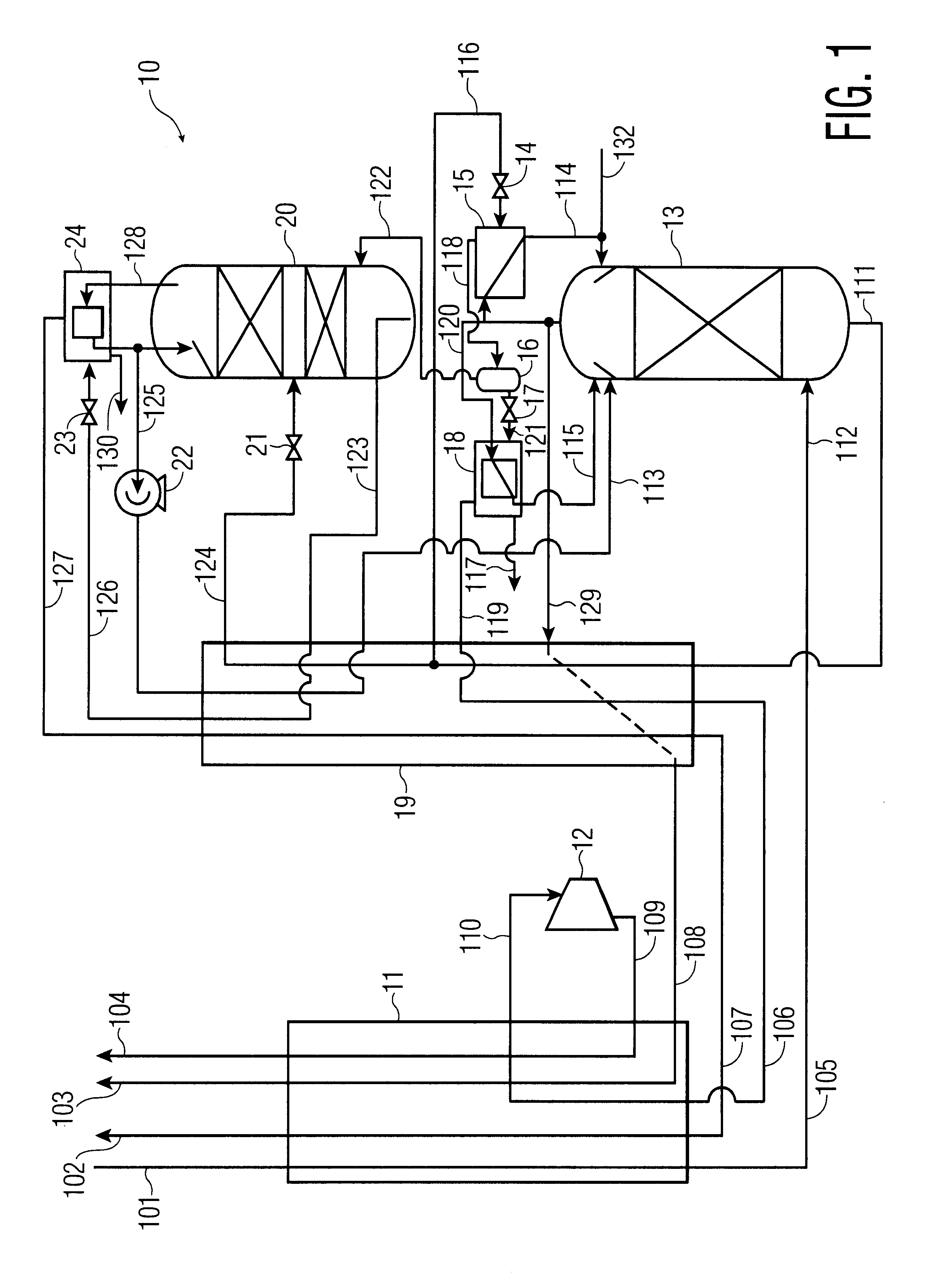
process for the recovery of substantially pure nitrogen at a rate of 2687 Nm3 / hr at a pressure of 4.9 atma is conducted in accordance with FIG. 1. Nm3 / hr refers to the flow rate of a substance measured as a gas at 0 C. and 1 atma. C. refers to temperature in degrees Celsius; atma refers to pressure in absolute atmospheres. K refers to temperature in degrees Kelvin.

A feed air flow of 4632 Nm3 / hr was compressed to a pressure of 5.2 atma, aftercooled to about ambient temperature, its water condensate removed, and passed to an adsorption unit for removal of water and carbon dioxide, and possibly other contaminants. The purified air 101 was passed to main heat exchanger 11 where it was cooled to approximately its dew point, producing a small amount of liquid. Air 105 entered the bottom of high pressure column 13 at 98.6 K and 5.05 atma. The high pressure column is internally made up of structured packing for mass transfer.

Gaseous nitrogen at a 94.1 K and 5.0 atma exited from the top of t...


PUM


Abstract

Nitrogen gas at a single pressure is produced from a two-column cryogenic distillation of air. The bottoms liquid product from the high pressure column is divided into portions, at least one of which does not enter the low pressure column as a feed stream. By these means, a portion of an oxygen-rich stream is removed from the distillation, further enhancing nitrogen recovery and achieving low specific energy consumption for nitrogen product.

Description

The present invention is directed to the cryogenic separation of air by distillation for the production of primarily gaseous nitrogen.Nitrogen is among the most heavily produced and used chemicals. It finds application in the petroleum, glass, foods, electronics, pharmaceutical, and metals industries. Cryogenic separation of air is a principal means of producing nitrogen.Cryogenic air separation plants, chiefly for the production of gaseous nitrogen, exist in a number of configurations. These, in turn, group around single distillation column and double distillation column designs. There are many variations of these designs in each category. In most cases the objective is to produce nitrogen at the lowest energy consumption for any given delivery pressure; but aspects such as capital cost and particular features of convenience are equally important.A simple single-column system has a relatively low nitrogen recovery, the balance of the air being discharged as an impure product contai...

Claims


Application Information

Patent Timeline
Patent Type & Authority Patents(United States)
IPC IPC(8): F25J3/04
CPCF25J3/04212F25J3/0423F25J3/04254F25J3/04284F25J3/04424F25J3/04884F25J2200/20F25J2205/02F25J2210/42F25J2235/42F25J2245/42F25J2250/02F25J2250/10F25J2250/20F25J2250/40F25J2250/42F25J2250/52
Inventor MOSTELLO, ROBERT ANTHONY
Owner AIR WATER GAS SOLUTIONS INC
Why Eureka
Try Eureka