Low-pressure mercury vapor discharge lamp and illuminator

a mercury vapor discharge and lamp technology, applied in the direction of discharge tube luminescnet screens, transit tube circuit elements, cathode-ray/electron beam tube circuit elements, etc., can solve the problems of low efficiency of lamp bulbs, high inner wall load of lamps, and low mercury vapor pressure drop

Inactive Publication Date: 2002-01-08
TOSHIBA LIGHTING & TECH CORP
View PDF22 Cites 46 Cited by
  • Summary
  • Abstract
  • Description
  • Claims
  • Application Information

AI Technical Summary

Benefits of technology

According to the present invention, the cold spot is formed at one end and mercury is filled by the mercury emission body and therefore, almost no excess mercury exists in the container, luminous flux starts up fast, mercury collected to the cold spot scarcely moves to other portions, and the lamp characteristic is stabilized.
Further, the startup of luminous flux referred to here does not imply such a temporary rise of luminous flux that luminous flux once rises after lighting a lamp, mercury vapor pressure also rises continuously while exceeding the maximum efficacy with subsequent temperature rise and luminous flux drops but it indicates the stable startup of luminous flux in a short time.

Problems solved by technology

On the other hand, a lamp that is lighting at a high atmospheric temperature or a lamp that has high inner wall load of the lamp bulb (input power per surface area of the bulb) is used at low efficiency because its temperature at the cold spot temperature of the bulb wall exceeds about 40.degree. C.
However, there is such a problem that when amalgam is applied to ordinary fluorescent lamps, mercury vapor pressure drops too low when starting, in particular at a low temperature, and the startup of luminous flux becomes worse.
Further, even if mercury was collected to the cold spot and the lamp characteristic was stabilized, mercury may move from the cold spot to other portion by a vibration applied to the lamp, etc. and the characteristic may be turned to the unstable state again.

Method used


Image

  • Low-pressure mercury vapor discharge lamp and illuminator
  • Low-pressure mercury vapor discharge lamp and illuminator
  • Low-pressure mercury vapor discharge lamp and illuminator

Examples


first embodiment

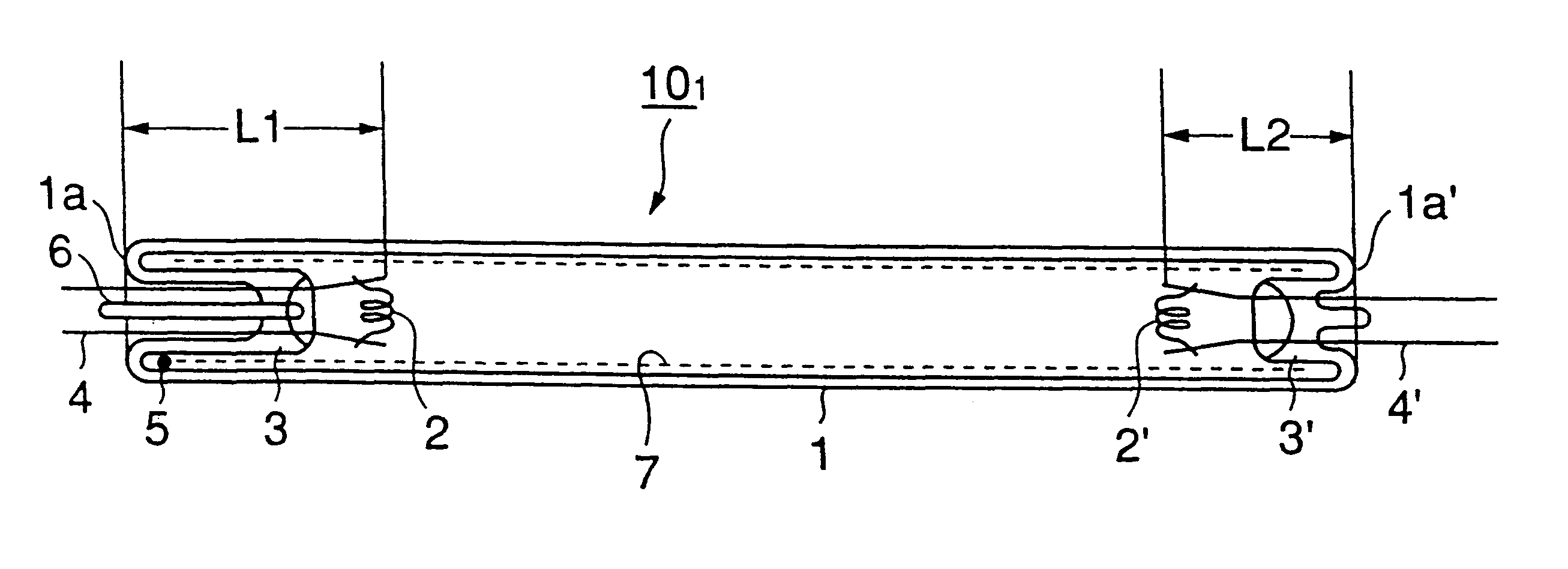
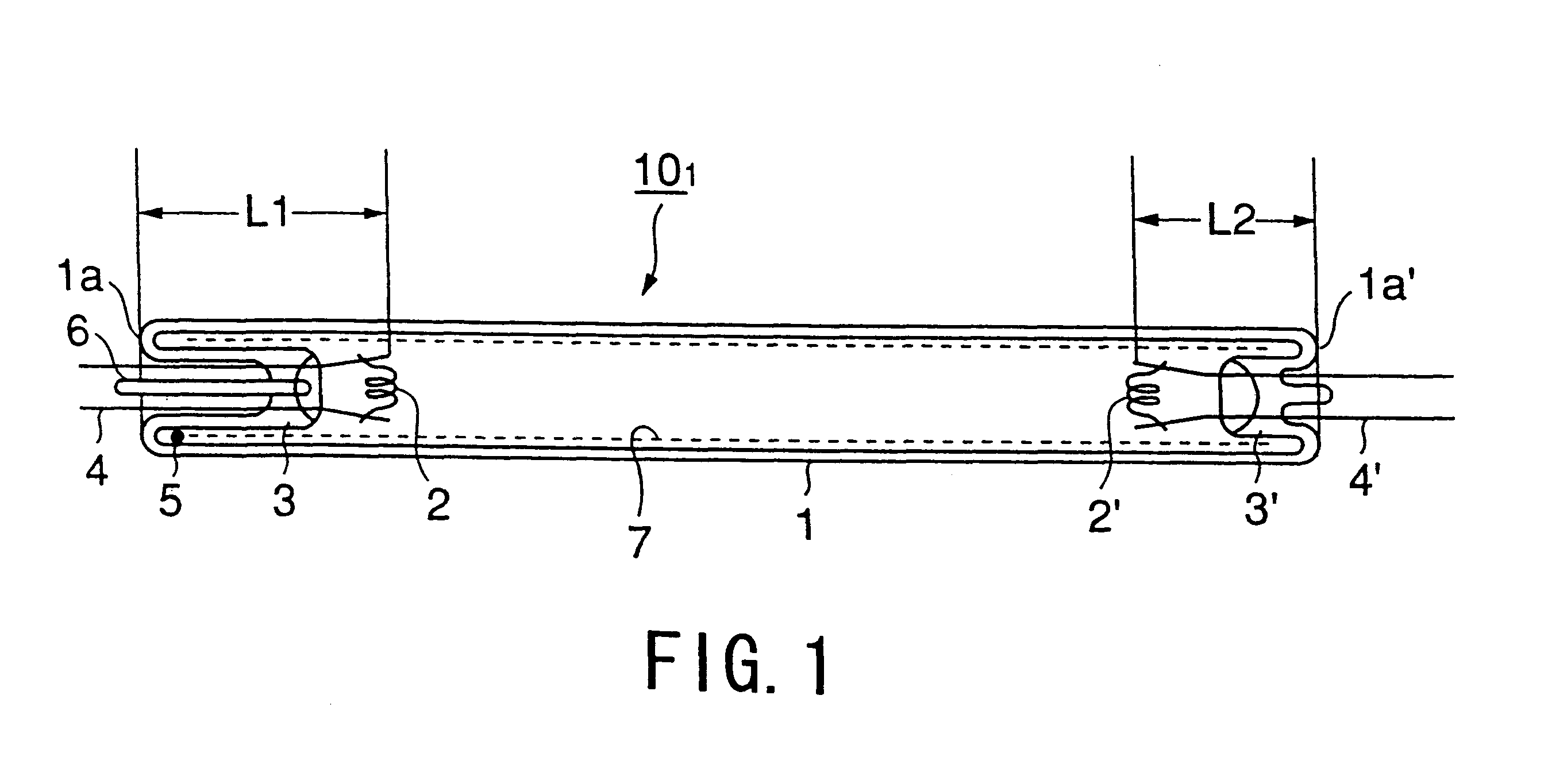
FIG. 1 is a schematic sectional view showing a fluorescent lamp in the present invention.

A fluorescent lamp 10.sub.1 in this embodiment is applied with input power of 24 W exclusively for high frequency lighting type.

A translucent airtight container 1 is made of a soda glass made long and narrow straight tube in a diameter about 16 mm and 549 mm long.

A pair of electrodes 2 and 2' are of hot-cathode type with a coil filament coated with an emitter and separately arranged opposing each other in the airtight container 1. These electrode pair 2 and 2' are sealed at both ends of the bulb by a flare stem (described later) in the bulb 1. That is, they are sealed by sealing portions 1a and 1a' formed at both ends.

A pair of the electrodes 2 and 2' are so arranged that a length L1 from the sealing portion 1a of the electrode 2 becomes longer by about 15 mm than a length L2 from the sealing portion 1a' of the other electrode 2'. Further, L1 in this embodiment is about 35 mm and L2 is about 20 ...

third embodiment

FIG. 8 is a schematic plan view of the double ring type fluorescent lamp in the

The double ring type fluorescent lamp 10.sub.3 is provided with airtight containers 1 and 1' as first and second ring type tubes, which are in different diameter each other. These airtight containers 1 and 1' are positioned in the shape of concentric circle on the same plane surface and connected by a bridge 8. Further, the inner diameter of these airtight containers 1 and 1' is about 18 mm and the outer diameters are 334 mm and 400 mm, respectively.

At one end side of these airtight containers 1 and 1', the first and second electrodes 2 and 2' are arranged. The bridge 8 is formed at the point 18-26 mm away from the other ends 1c and 1c' of the airtight containers 1 and 1' so as to produce a discharge space to cause the discharge between the electrodes 2 and 2'.

Between the bridge 8 and the other ends 1c and 1c' of the airtight containers 1 and 1', there is a no-discharge path formed area 13 wherein no disc...

second embodiment

On the inner surface of the airtight container 1' in the no-discharge path formed area 13, the granulated mercury emission body 5 comprising a zinc-mercury alloy of 1 mm in diameter is fixed likewise the

The base 9 is installed over one ends and the other ends 1c and 1c' of the airtight container 1 and 1'. Further, the base 9 is installed on the airtight containers 1 and 1' so as not to cover the bridge 8 and a part of the no-discharge path formed area 13.

In case of the double ring type fluorescent lamp 10.sub.3 in the third embodiment, the cold spot is formed in the no-discharge path formed area 13 with the lighting of the fluorescent lamp likewise the above-mentioned embodiments, mercury in the airtight containers 1 and 1' is quickly collected to the cold spot by diffusion of mercury vapor, luminous flux starts up fast and the lamp characteristic is stabilized. As an amount of mercury in the airtight containers is as small as about 6 mg, the mercury collected at the cold spot is no...


PUM


Abstract

A low-pressure mercury vapor discharge lamp (101) includes a translucent airtight container (1), a pair of electrodes (2) and (2') mounted in the airtight container (1) and arranged at both ends and so that a distance of one of the electrodes from the sealing portions (1a) and (1a') becomes longer than that of the other electrode, a mercury emission body (5) filled in the airtight container and discharge medium including mercury discharged from the mercury emission body (5) and inert gas. A cold spot is formed at one sealing portion (1a) of the low-pressure mercury vapor discharge lamp (10) and mercury is filled by the mercury emission body (5) and therefore, there is almost no excess mercury existing in the tube (1), luminous flux starts up fast, mercury collected in the cold spot scarcely moves to other portion, and the lamp characteristic is stabilized.

Description

This application is the national phase of international application PCT / JP99 / 05143 filed Sep. 21, 1999 which designated the U.S.The present invention relates to a low-pressure mercury vapor discharge lamp equipped with a pair of electrodes arranged in different distances from both ends of an airtight container and a lighting system.It is known that a low-pressure mercury vapor discharge lamp represented by a fluorescent lamp that lights at the most high efficiency when mercury vapor pressure in the bulb is about 0.8 Pa. The cold spot temperature of the bulb wall at this time is about 40.degree. C.On the other hand, a lamp that is lighting at a high atmospheric temperature or a lamp that has high inner wall load of the lamp bulb (input power per surface area of the bulb) is used at low efficiency because its temperature at the cold spot temperature of the bulb wall exceeds about 40.degree. C. As a measure to improve efficiency of a lamp lighting at a high temperature of the cold spot...

Claims


Application Information

Patent Timeline
Patent Type & Authority Patents(United States)
IPC IPC(8): H01J61/28H01J61/12H01J61/20H01J61/24H01J61/32H01J61/72
CPCH01J61/20H01J61/72H01J61/322H01J61/24
Inventor YORIFUJI, TAKASHISUGIYAMA, KENJINAKAMURA, TOSHIYUKIYAMADA, ICHIRO
Owner TOSHIBA LIGHTING & TECH CORP
Why Eureka
Try Eureka