
Vapochromic LED

Inactive Publication Date: 2002-01-15
RGT UNIV OF MINNESOTA
View PDF2 Cites 29 Cited by
  • Summary
  • Abstract
  • Description
  • Claims
  • Application Information

AI Technical Summary

Problems solved by technology

However, to the best of the inventors' knowledge, there is only one unspecific report from the patent literature which describes this type of LED sensor; see, U.S. Pat. No. 5,629,533, issued to D. E. Ackley et al on May 13, 1997.

Method used


Image

  • Vapochromic LED
  • Vapochromic LED
  • Vapochromic LED

Examples


Embodiment Construction

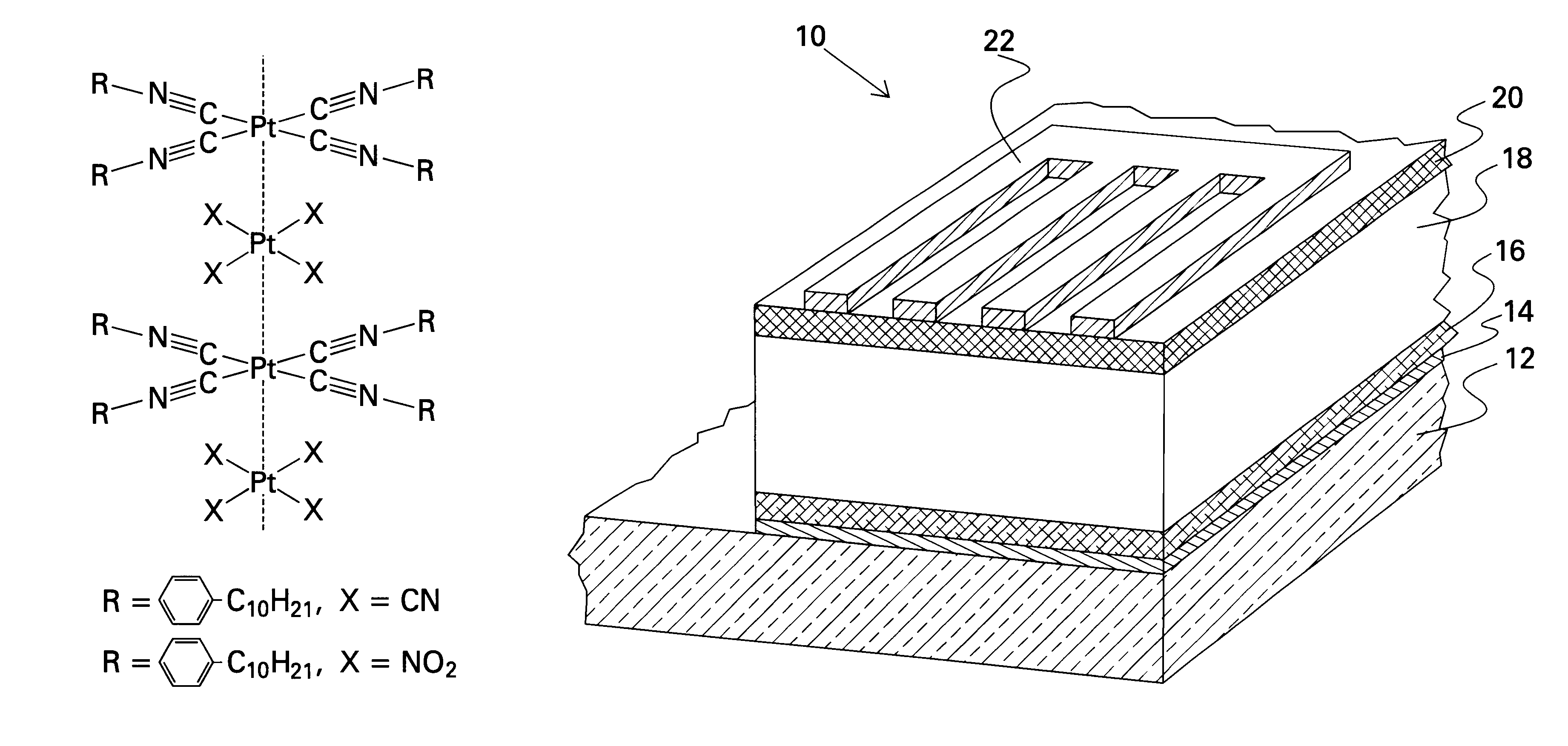
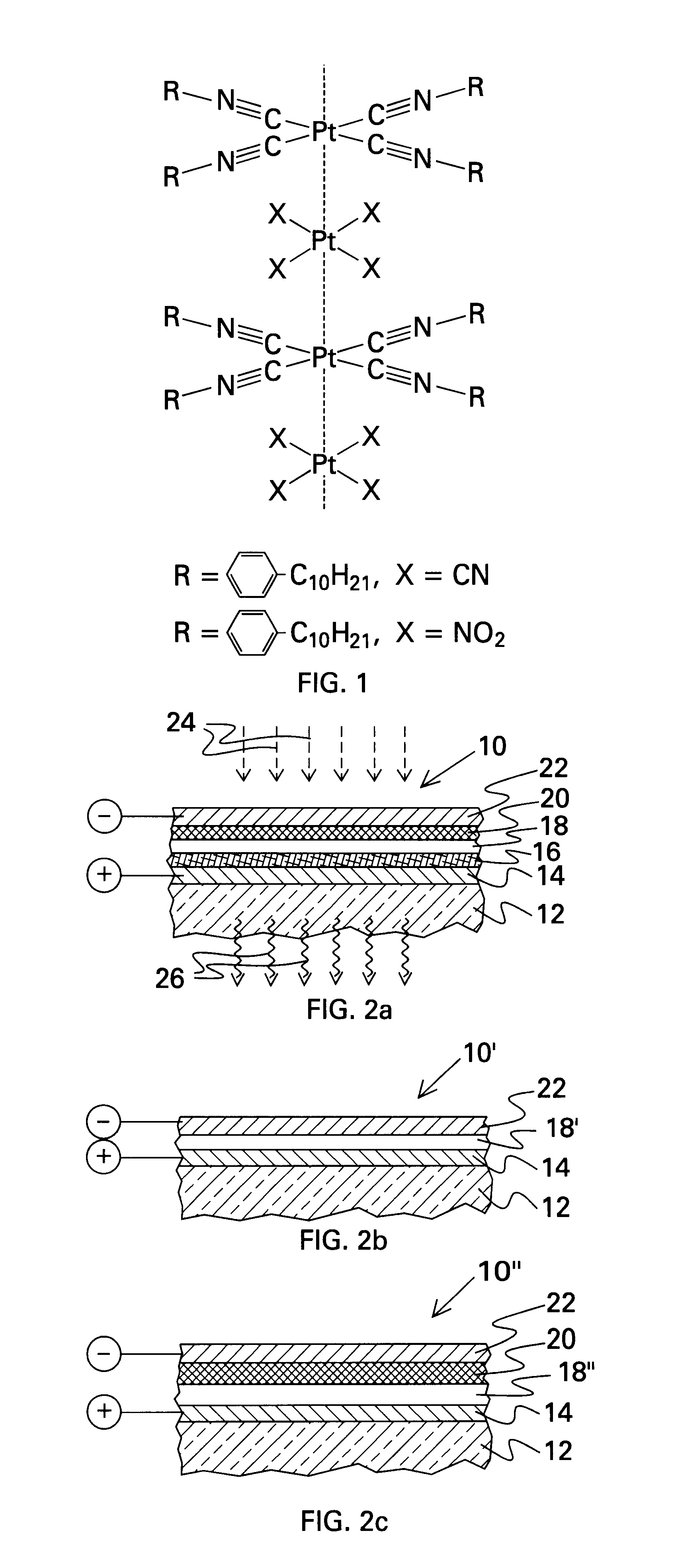
In accordance with the present invention, a vapochromic light emitting diode is provided, which is sensitive to certain organic vapors and emits optical radiation upon exposure to the organic vapor. Referring to FIG. 2a, the general structure of the LED 10 is formed on a substrate 12 and comprises:

(a) a first electrode 14 formed on the substrate;

(b) a hole transport layer 16 formed on the first electrode;

(c) a sensing / emitting layer 18 formed on the hole transport layer;

(d) an electron conductor layer 20 formed on the sensing / emitting layer; and

(e) a second electrode 22 formed on the electron conductor layer.

The material comprising the substrate 12 comprises any optically transparent dielectric material having sufficient thickness and strength to support the layers formed thereover. An example of a suitable substrate material includes quartz.

The first electrode 14 comprises indium tin oxide (ITO) or polyaniline or other such material that is both electrically conductive and transpar...


PUM

PropertyMeasurementUnit
wavelengthaaaaaaaaaa
diameteraaaaaaaaaa
colorsaaaaaaaaaa

Abstract

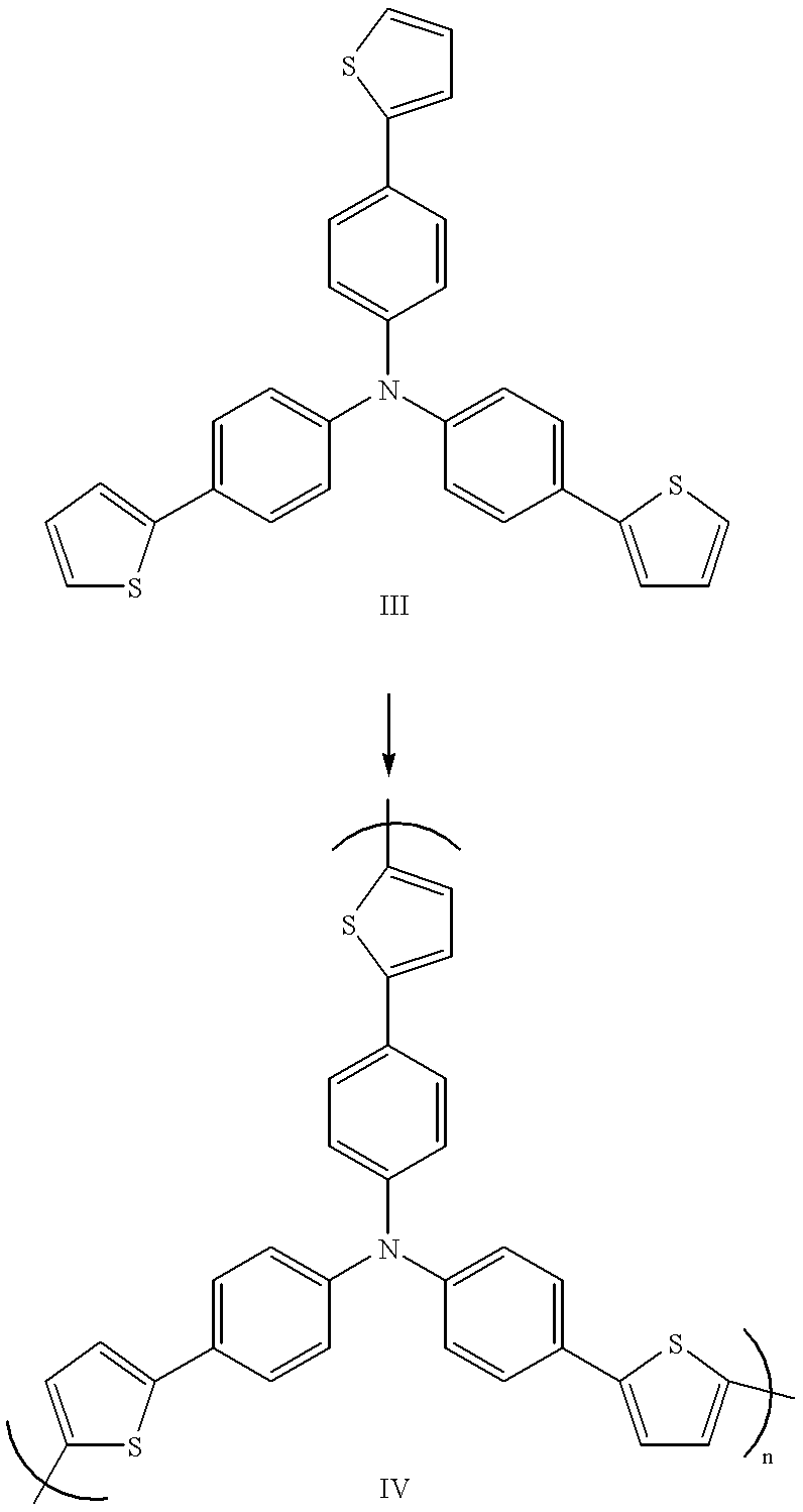
A sandwich device was prepared by electrodeposition of an insoluble layer of oligomerized tris(4-(2-thienyl)phenyl)amine onto conducting indium-tin oxide coated glass, spin coating the stacked platinum compound, tetrakis(p-decylphenylisocyano)platinum tetranitroplatinate, from toluene onto the oligomer layer, and then coating the platinum complex with aluminum by vapor deposition. This device showed rectification of current and gave electroluminescence. The electroluminescence spectrum (mumax=545 nm) corresponded to the photoluminescence spectrum of the platinum complex. Exposure of the device to acetone vapor caused the electroemission to shift to 575 nm. Exposure to toluene vapor caused a return to the original spectrum. These results demonstrate a new type of sensor that reports the arrival of organic vapors with an electroluminescent signal. The sensor comprises (a) a first electrode; (b) a hole transport layer formed on the first electrode; (c) a sensing / emitting layer formed on the hole transport layer, the sensing / emitting layer comprising a material that changes color upon exposure to the analyte vapors; (d) an electron conductor layer formed on the sensing layer; and (e) a second electrode formed on the electron conductor layer. The hole transport layer emits light at a shorter wavelength than the sensing / emitting layer and at least the first electrode comprises an optically transparent material.

Description

The present invention relates generally to molecular electronics, and, more particularly, to vapor-sensitive, molecular light emitting diodes based on thin films of certain platinum complexes.The inventors have recently published reports that have enucleated and explained the unusual "vapochromic" changes in absorption and emission spectra that result when certain stacked platinum complexes are exposed to organic vapors; see, e.g., C. L. Exstrom et al, Chemical Materials, Vol. 7, pp. 15-17 (1995) and C. A. Daws et al, Chemical Materials, Vol. 9, pp. 363-368 (1997).A typical experiment involves a solution, crystal or solid film of material, such as tetrakis(p-decylphenylisocyano)platinum tetracyanoplatinate (I) (see FIG. 1, which depicts the chemical formula of the compound, where the dashed vertical line indicates the c-axis) that forms stacks of alternating cations and anions with strong inter-platinum interactions. These salts exhibit an intense absorption band in the visible regi...

Claims


Application Information

Patent Timeline
Patent Type & Authority Patents(United States)
IPC IPC(8): H01L51/40H01L51/05H01L51/30H01L51/00
CPCH01L51/0006H01L51/0059H01L51/0061H01L51/009H01L51/424H01L51/0087H01L51/0036Y02E10/549H01L51/441H01L2251/308H10K71/125H10K85/113H10K85/631H10K85/636H10K85/346H10K85/361H10K30/20H10K30/81H10K2102/103
Inventor KUNUGI, YOSHIHITOMANN, KENT R.MILLER, LARRY L.EXSTROM, CHRISTOPHER L.
Owner RGT UNIV OF MINNESOTA
Learn More