Vector control method for synchronous reluctance motor

a synchronous reluctance motor and control method technology, applied in the direction of motor/generator/converter stopper, dynamo-electric converter control, dynamo-electric gear control, etc., can solve the problem of deteriorating the reliability of the motor system, affecting the accuracy of cosine estimation, and affecting the reliability of the motor body. , to achieve the effect of accurate and efficient estimation

Inactive Publication Date: 2002-01-15
OKUMA CORP
View PDF5 Cites 32 Cited by
  • Summary
  • Abstract
  • Description
  • Claims
  • Application Information

AI Technical Summary

Benefits of technology

is to provide a novel vector control method which does not require the salient pole position angle detector such as an encoder for a synchronous reluctance motor in order to solve the aforesaid problems related to the synchronous reluctance motor drive control. More particularly, it is the object of the present invention to provide a vector control method that can accurately and efficiently estimate cosine and sine signals as rotation signals for the vector rotators.
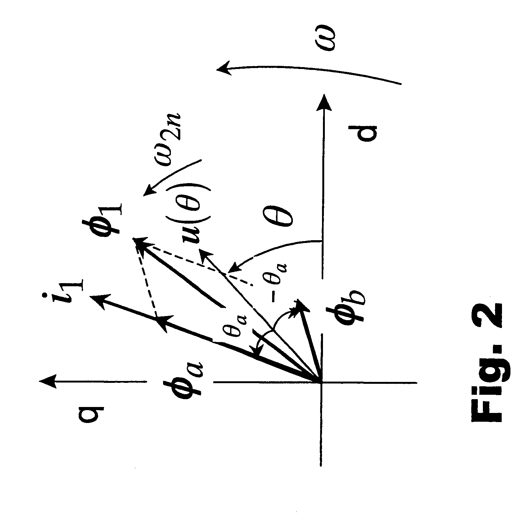
According to another aspect, the present invention is a vector control method as above, wherein the estimates of cosine and sine of the double angle of the intermediate angle are determined from the in-phase flux vector or its estimate value and the mirror-phase flux vector or its estimate value, and the estimates of cosine and sine of the intermediate angle are determined from the determined estimates of cosine and sine of the double angle. It is apparent from the above description with reference to the equations (16) and (17) that the present invention can provide the direct calculation of the estimates of cosine and sine necessary for the vector rotators from the in-phase and mirror-phase flux vectors themselves without calculating the position angles of the in-phase flux vector and the mirror-phase flux vector. The calculation of the position angle from the vectors requires an inverse operation of a trigonometric function that is a kind of nonlinear functions. It is known that the inverse operation might cause a great error or need a large amount of computation depending on the position angle. In this aspect of the present invention, however, such an inverse operation is not necessary, and estimates of cosine and sine of the position angle can be determined with relatively high accuracy by a relatively light calculation. In other words, according to this aspect of the present invention, the operation described earlier can be obtained with relatively high accuracy by a relatively light calculation.
In a further aspect of the vector control method as described above, the method of determining the estimates of cosine and sine of the intermediate angle from the estimates of cosine and sine of the double angle is varied according to a predicted magnitude of the estimates of cosine and sine of the intermediate angle. As a result, it is apparent from the above description, referring to the equations (18) and (19), that there is obtained an operation that the estimates of cosine and sine can be determined as the rotation signal for the vector rotators in the state maintaining the highest computation accuracy, as well as in the state that the amount of computation is reduced rationally. In addition, according to this aspect of the present invention, the operation described above can be obtained with a high accuracy and a rationalized amount of calculation.
According to the present aspect, it is apparent from the above description referring to the equation (21) that there is obtained an operation that the estimates of cosine and sine of the intermediate angle and further the rotation signal necessary for the vector rotators can be determined by very simple calculation excepting an area where the absolute value of the inner product (i.sub.1.sup.T u(.theta.)) of the stator current and the unit vector becomes small. As a result, according to the present aspect, the operation described can be achieved by very simple calculation. A method of avoiding the absolute value of the inner product of the stator current and the unit vector from becoming too small will be described in detail below with reference to an embodiment related to the present aspect.

Problems solved by technology

However, fitting of the salient pole position angle detector such as an encoder to the rotor leads to the certain heretofore unavoidable problems, as described below.
A first problem is the deterioration in the reliability of the motor system.
Although mechanically the synchronous reluctance motor is one of the strongest types of AC motor, as can be seen from the structure of the rotor, the salient pole position angle detector such as an encoder is mechanically much weaker than the motor body.
Consequently, the placement of the salient pole position angle detector decreases extremely the overall mechanical reliability of the motor system.
In addition to the deterioration in the mechanical reliability, the reliability decrease of the motor system due to the fitting of the salient pole position angle detector also occurs in an electrical aspect observed as contamination of the salient pole position angle detector signal with power supply noise, and also a thermal aspect observed as a temperature increase in the salient pole position angle detector due to heat from the rotor.
Thus, the attachment of the salient pole position angle detector such as an encoder to the motor rotor has extremely decreased the reliability of the motor system.
A second problem is increase in motor size.
A third problem is the necessity to secure a source of power for operating the salient pole position angle detector, wiring of a signal line to receive a detection signal and a space for wiring.
A fourth problem is an increase in cost.
In the production of a compact motor, the cost of the salient pole position angle detector might become higher than that of the motor body.
Also, the cost of wiring for the salient pole position angle detector cannot be disregarded, especially for a compact motor.
Maintenance costs also inevitably increase when reliability decreases.
These various costs increase according to the number of motors used.
Especially, the maintenance cost has a property of increasing exponentially in proportion to the quantity of motors.
Development of a sensorless vector control method for the synchronous reluctance motor is expected, but has not yet been reduced to practice.
It is known that the inverse operation might cause a great error or need a large amount of computation depending on the position angle.

Method used


Image

  • Vector control method for synchronous reluctance motor
  • Vector control method for synchronous reluctance motor
  • Vector control method for synchronous reluctance motor

Examples


first embodiment

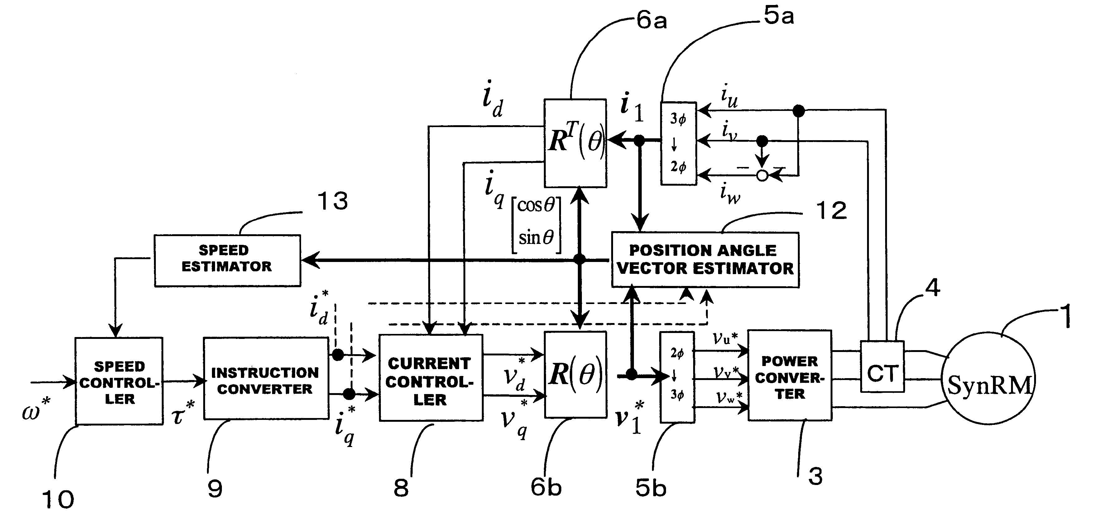
FIG. 8 shows the cosine and sine generator 12b. In the drawing, 12b-1 is a double angle cosine and sine generator and 12b-2 is an intermediate angle cosine and sine generator. And, 12b-3 is a judging device which generates a selection signal to be used for selection of a determination method by the intermediate angle cosine and sine generator.

The double angle cosine and sine generator receives as input the estimates of the in-phase flux vector and the mirror-phase flux vector, determines the estimates of cosine and sine of the double angle of the intermediate angle of both vectors and outputs them. This estimate value determination processing is performed according to the equation (16). The intermediate angle cosine and sine generator 12b-2 receives as input the cosine and sine estimates of the double angle output from the double angle cosine and sine generator 12b-1 and uses them to determine and output the estimates of cosine and sine of the intermediate angle.

According to the pre...

second embodiment

FIG. 10 shows the cosine and sine generator 12b. In this drawing, 12b-4 is a vector addition synthesizer. The vector addition synthesizer multiplies the estimate value of the in-phase flux vector and the estimate value of the mirror-phase flux vector by the reciprocal of their respective inductances, makes its norm the same, and then generates and outputs a synthesis vector by adding the vectors. In the vector addition synthesizer, K.sub.2 is a design parameter whose design is entrusted to a designer and may be generally selected as desired but can be preferably selected to be 1, L.sub.a or L.sub.b. In FIG. 10, 12b-5 is a vector normalization device for the additive synthesis vector and determines the estimates of cosine and sine of the intermediate angle in proportion to the synthesis vector. In this embodiment, the vector having the cosine and sine values of the intermediate angle as first and second components is a unit vector, so that such a unit property is used to normalize th...

third embodiment

FIG. 11 is the cosine and sine generator 12b. In the drawing, 12b-6 denotes a vector subtraction synthesizer. The vector subtraction synthesizer multiplies the estimate value of the in-phase flux vector and the estimate value of the mirror-phase flux vector by the reciprocal of each related inductance to make the norm the same, and performs vector subtraction to generate and output a synthesis vector. In the vector subtraction synthesizer, K.sub.2 is a design parameter whose design is entrusted to the designer and generally selected as desired, with 1, L.sub.a, L.sub.b being preferable candidate values. In FIG. 11, 12b-7 is a vector normalization device for the subtraction synthesis vector and decides the estimates of cosine and sine of the intermediate angle in skewed proportion to the synthesis vector. In this embodiment, the vector having the estimates of cosine and sine of the intermediate angle as first and second components is a unit vector, and the estimates of cosine and sin...


PUM


Abstract

In a driving control method for a synchronous reluctance motor, a novel vector control method is employed which does not need the salient pole position angle detector. More particularly, the present invention provides a vector control method which can accurately and efficiently estimate cosine and sine signals, being rotation signals for the vector rotators.A flux vector estimator 12a uses voltage and current information of a stator to estimate a stator flux vector by dividing it into an in-phase flux vector having the same direction as a current vector and a mirror-phase flux vector determined as a difference between the stator flux vector and the in-phase flux vector. A cosine and sine generator 12b uses the estimated in-phase and mirror-phase flux vectors to generate the cosine and sine values of an intermediate angle of the angles of such flux vectors and outputs a rotation signal of the vector rotators. Thus, vector control is established.

Description

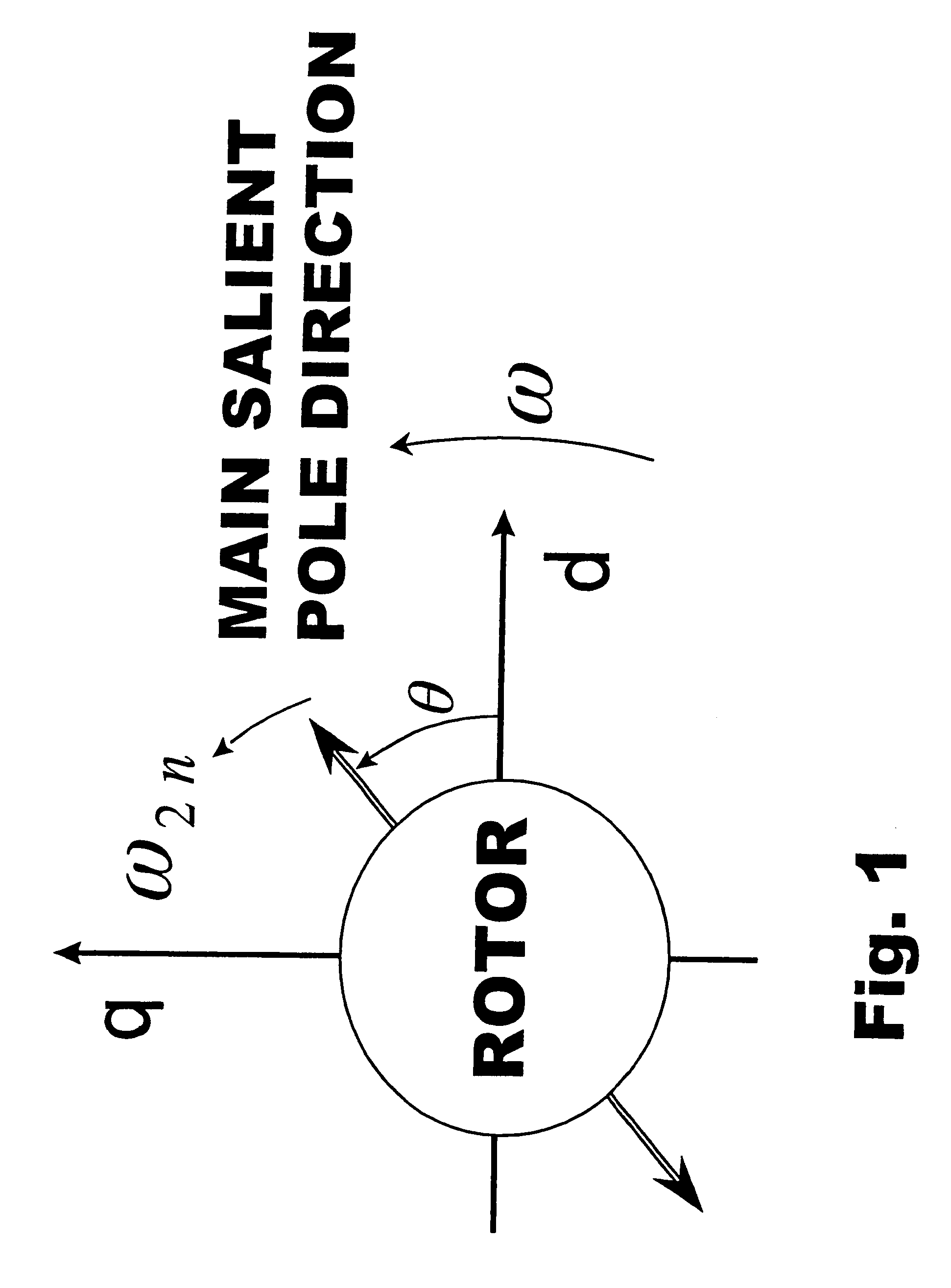
1. Field of the InventionThe present invention relates to a vector control method for a synchronous reluctance motor. More particularly, the invention relates to a vector control method using an estimator, instead of a salient pole position angle detector mounted on a rotor, in order to secure cosine and sine information of a rotor's salient pole position angle necessary for a vector rotators for the vector control.2. Description of the Related ArtTo obtain superior drive control performance of a synchronous reluctance motor, the vector control method is conventionally employed as a well-known control method for controlling a stator current, which is essential for superior performance. The vector control method has a current control process which divides and controls the stator current contributing to the generation of a torque into a d-axis component and a q-axis component of rotational d-q coordinates composed of mutually orthogonal d and q axes which mutually cross at right angle...

Claims


Application Information

Patent Timeline
Patent Type & Authority Patents(United States)
IPC IPC(8): H02P25/08H02P25/02H02P21/12H02P21/14H02P21/00H02P21/18H02P21/22H02P21/24H02P21/28H02P23/14H02P27/04
CPCH02P21/12H02P21/18H02P25/089
Inventor SHINNAKA, SHINJI
Owner OKUMA CORP
Why Eureka
Try Eureka