
Digital multi-channel demultiplexer/multiplexer (MCD/M) architecture

a multi-channel demultiplexer and multi-channel technology, applied in frequency-division multiplex, orthogonal multiplex, instruments, etc., can solve the problems of inability to physically realize polyphase filters, inability to accurately achieve high-order prototype filters, and inability to place stringent constraints on power, mass,

Inactive Publication Date: 2002-02-26
TAMIRAS PER PTE LTD LLC
View PDF17 Cites 23 Cited by
  • Summary
  • Abstract
  • Description
  • Claims
  • Application Information

AI Technical Summary

Benefits of technology

Briefly, this invention contemplates the provision of a digital signal processing system for multiplexing / demultiplexing a large number of closely spaced FDM channels in which sub-band definition filtering divides the FDM channel band comprised of "N" channels into "K" sub-bands in order to reduce the dimension of the polyphase filter-fast Fourier transform structure required to complete the multiplexing / demultiplexing. This reduces the order of the required prototype filter by a factor proportional to K. The number of sub-bands K is chosen so that it is large enough to ensure the polyphase filter-fast Fourier transform structure for each sub-band is realizable within a finite word length, fixed point arithmetic implementation compatible with a low power consumption. To facilitate efficient sub-band definition filtering, the real basebanded composite signal is inputted at a spectral offset from DC equal to one half the aggregate FDM channel bandwidth for the N channels and the signal is sampled at a frequency 100% greater than the applicable Nyquist rate. The half band spectral offset and oversampling by 100% above the theoretical Nyquist rate facilitate the use of computationally efficient bandshift and symmetric half-band Finite Impulse Response (FIR) filtering.

Problems solved by technology

Such systems (e.g., satellite based cellular systems) often place stringent constraints on the power, mass and physical dimensions of the digital MCD / M subsystem designed to generate the constituent FDM communications channels.
Short sample word lengths and fixed point arithmetic are, however, inherently incompatible with accurate, high order prototype filter realizations.
Indeed, in some applications, the indicated (higher order prototype) polyphase filter may not even be physically realizable within the finite word length and fixed point arithmetic dimensions necessary to meet the MCD / M subsystem's power, mass and size constraints.

Method used


Image

  • Digital multi-channel demultiplexer/multiplexer (MCD/M) architecture
  • Digital multi-channel demultiplexer/multiplexer (MCD/M) architecture
  • Digital multi-channel demultiplexer/multiplexer (MCD/M) architecture

Examples


Embodiment Construction

A preferred embodiment of the invention is discussed in detail below. While specific implementations are discussed, it should be understood that this is done for illustration purposes only. A person skilled in the relevant art can recognize that other components and configurations may be used without parting from the spirit and scope of the invention.

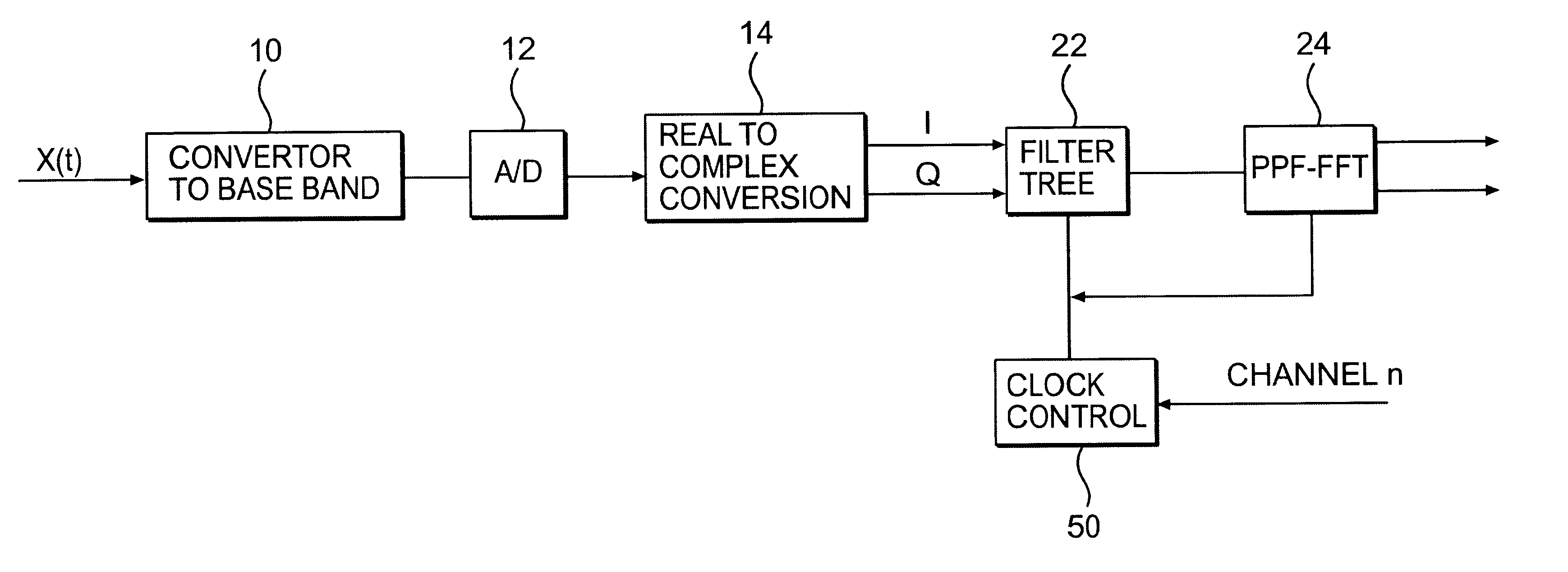
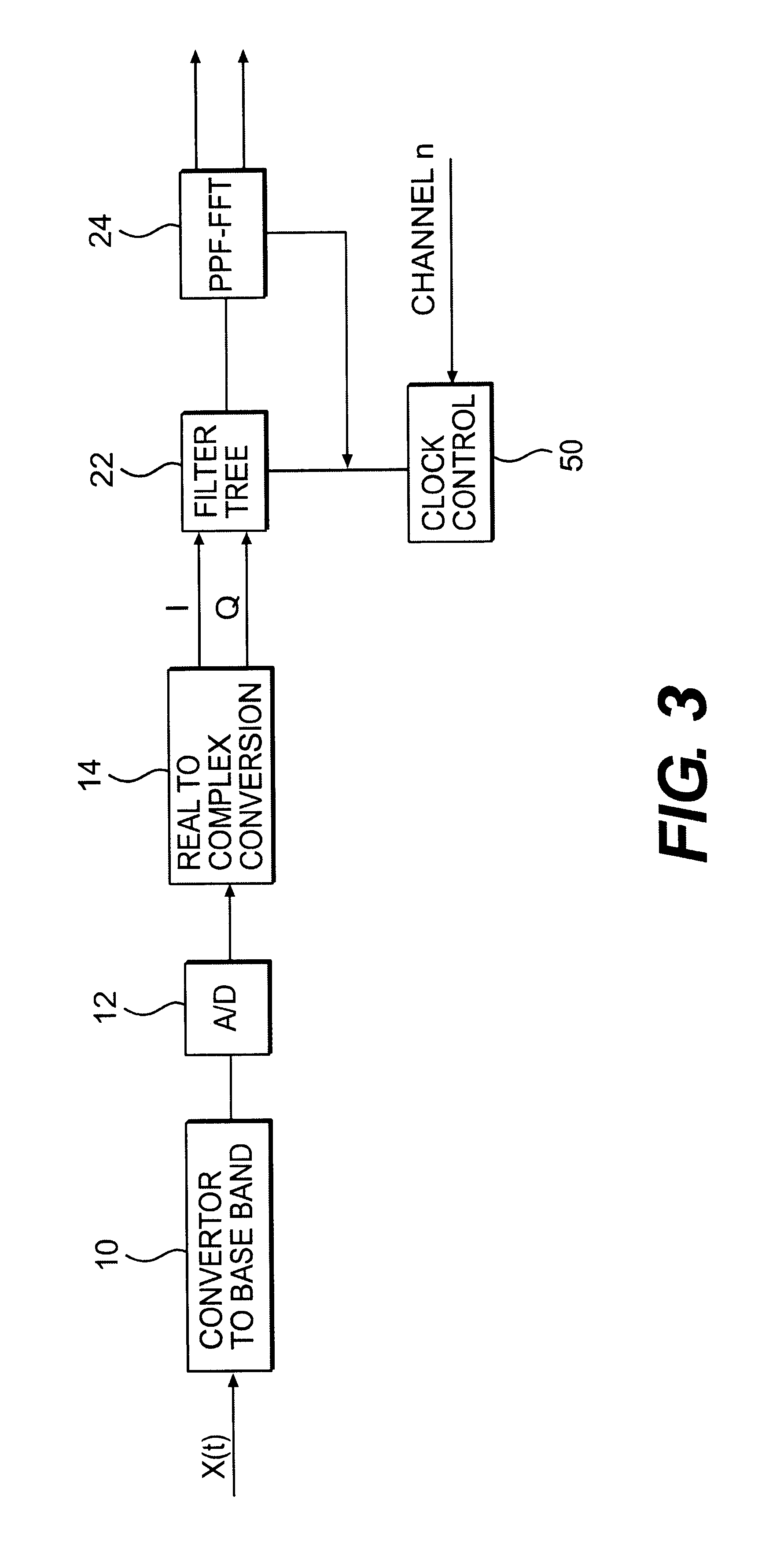
Referring now to FIGS. 3 and 4, an RF, N channel FDM signal X(t) of bandwidth B is coupled to the input of an RF to baseband down convertor stage 10, which converts the received RF signal to a baseband signal off-set from DC by one half of the FDM signal bandwidth B, as illustrated in FIG. 4. That is, the center frequency of the basebanded signal is equal to the bandwidth B. As will be appreciated by those skilled in the art, prior art digital multi-channel multiplex and demultiplex signal processing systems accept their composite input signals, consisting of up to N constituent FDM communications channels, centered at a practical baseb...


PUM


Abstract

A computationally efficient digital signal processing (DSP) system is provided for multiplexing / demultiplexing a large number of closely spaced FDM channels. Sub-band definition filtering divides the FDM channel band, comprised of N channels into K sub-bands, in order to reduce the dimension of polyphase filter fast-Fourier transform for completing the multiplexing / demultiplexing. This reduces the order of the required prototype by a factor proportional to K and allows small size, lightweight DSP implementations.

Description

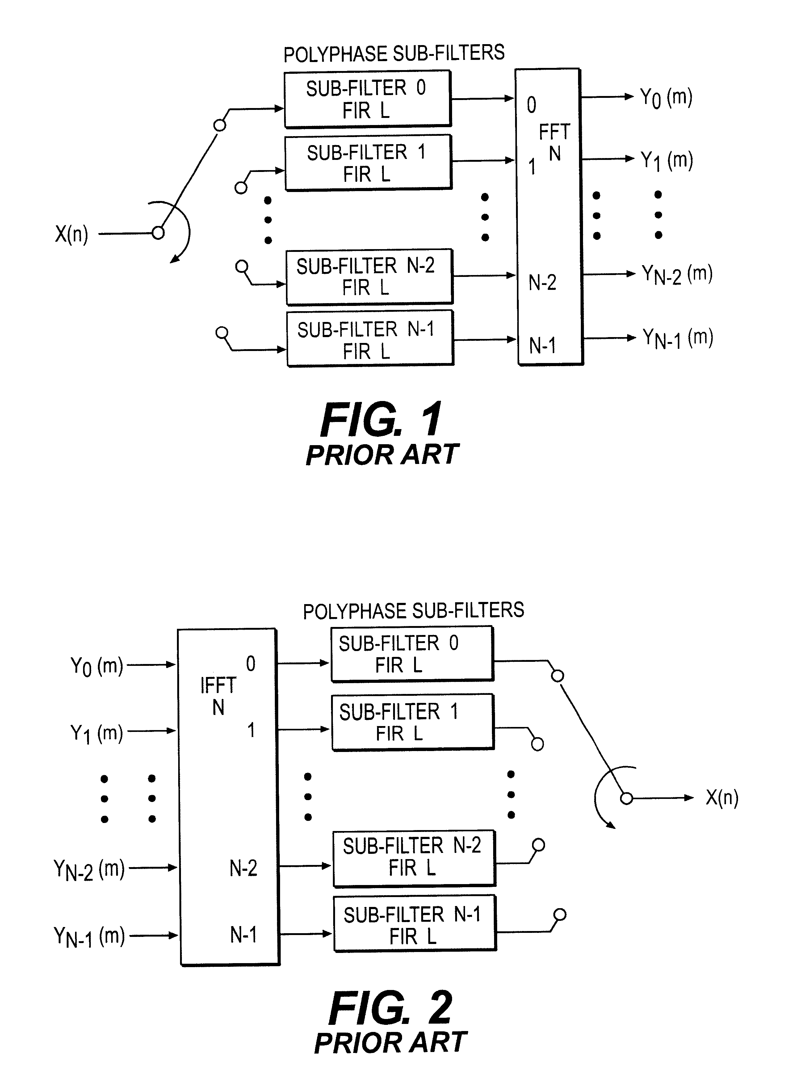
1. Field of the InventionThis invention relates to an improved digital signal processing method and apparatus for demultiplexing and multiplexing frequency division multiplexed channels and more particularly, to a lightweight, compact, low power system which synthesizes a polyphase filter, fast Fourier transform architecture suitable for use in applications with a large number of channels.2. Related ArtIn the prior art, digital polyphase filters (PPFs) are used in combination with fast Fourier transform (FFT) algorithms to efficiently demultiplex multiple, frequency division multiplexed (FDM) channels. Similarly, the polyphase filters are used in combination with inverse FFT algorithms to multiplex separate signals onto FDM channels. An N branch polyphase filter is realized by factoring (or partitioning) a desired prototype filter's transfer function (or impulse response) into N sub-filters. When coupled with an N point FFT (or IFFT) as shown in FIGS. 1 and 2, an N branch PPF can be...

Claims


Application Information

Patent Timeline
Patent Type & Authority Patents(United States)
IPC IPC(8): H04L5/02H04J1/05H04L5/06H04J1/00H03H17/02
CPCH03H17/0266H04L5/06H04J1/05
Inventor BUTASH, THOMAS C.
Owner TAMIRAS PER PTE LTD LLC
Learn More