Organic electroluminescence element

a technology of electroluminescence element and organic material, which is applied in the direction of discharge tube luminescnet screen, natural mineral layered products, transportation and packaging, etc., can solve the problems of insufficient heat resistance of organic materials, inability to obtain uniform and sufficient luminance for a long time, etc., and achieve stable luminance and high luminance

Inactive Publication Date: 2002-03-19
SANYO ELECTRIC CO LTD
View PDF2 Cites 62 Cited by
  • Summary
  • Abstract
  • Description
  • Claims
  • Application Information

AI Technical Summary

Benefits of technology

Examples will be given to specifically describe the organic electroluminescent device according to the present invention, and comparative examples will be given to clarify t...

Problems solved by technology

In a conventional organic electroluminescent device, however, it is generally difficult to obtain as an organic material used for its emitting layer high-purity one by sublimation and purification, for example, and the stability of the organic material to heat or the like is not sufficient.
When the organic electroluminescent device emits light for a long time, therefore, some problems occur.
For example, the organic material used...

Method used


Image

  • Organic electroluminescence element
  • Organic electroluminescence element
  • Organic electroluminescence element

Examples


examples 2 to 7

and

Comparative Examples 3 and 4

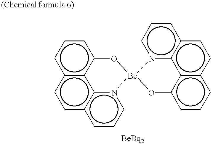
Also in organic electroluminescent devices in examples 2 to 7 and comparative examples 3 and 4, only the emitting layer 4 in the organic electroluminescent device in the above-mentioned example 1 was changed, and bis(10-hydroxybenzo[h]-quinolinate)beryllium (hereinafter referred to as BeBq.sub.2) indicated by the following chemical formula 6 was used as a host material. ##STR3##

The organic electroluminescent devices in the examples 2 to 7 and the comparative examples 3 and 4 were obtained in the same manner that in the example 1 except that an emitting layer 4 was formed using only the above-mentioned host material in the comparative example 3, while 2',3'-naphtha-2,3-fluorenone indicated by the following chemical formula 7, 2,3-anthrafluorene indicated by the following chemical formula 8, 2,3-benzofluorenone indicated by the following chemical formula 9, picene indicated by the following chemical formula 10, ovalene indicated by the following chemical...

examples 8 to 19

and

Comparative Examples 5 and 6

Also in organic electroluminescent devices in examples 8 to 19 and comparative examples 5 and 6, only the emitting layer 4 in the organic electroluminescent device in the above-mentioned example 1 was changed, and 1AZM-Hex indicated by the following chemical formula 14 was used as a host material. ##STR5##

The organic electroluminescent devices in the examples 8 to 19 and the comparative examples 5 and 6 were obtained in the same manner that in the example 1 except that an emitting layer 4 was formed using only the above-mentioned host material in the comparative example 5, while 1',2'-naphtha-2,3,-fluorene indicated by the following chemical formula 15, 2',1'-naphtha-1,2-fluorene indicated by the following chemical formula 16, 1,12-benzperylene indicated by the following chemical formula 17, 4,5-benzpyrene indicated by the following chemical formula 18, benzo(a)pyrene indicated by the following chemical 19, naphthapyrene indicated by the following chem...

example 20 to 31

and

Comparative Examples 7 and 8

Also in organic electroluminescent devices in examples 20 to 31 and comparative examples 7 and 8, only the emitting layer 4 in the organic electroluminescent device in the above-mentioned example 1 was changed, and tris(8-quinolinol)aluminum (hereinafter referred to as Alq.sub.3) indicated by the following chemical formula 28 was used as a host material. ##STR8##

The organic electroluminescent devices in the examples 20 to 31 and the comparative examples 7 and 8 were obtained in the same manner that in the example 1 except that an emitting layer 4 was formed using only the above-mentioned host material in the comparative example 7, while 1',2'-naphtha-2,3-fluorenone indicated by the following chemical formula 29, 2',1'-naphtha-1,2-fluorenone indicated by the following chemical formula 30, rubicene indicated by the following chemical formula 31, 1,2-benzpentacene indicated by the following chemical formula 32, 5,6,11,12-tetraphenyl naphthacene (rubrene) ...


PUM

PropertyMeasurementUnit
Energyaaaaaaaaaa
Energyaaaaaaaaaa
Energyaaaaaaaaaa

Abstract

In an organic electroluminescent device constructed by providing at least an emitting layer using an organic material between a hole injection electrode and an electron injection electrode, in forming an emitting layer having a dopant doped into a host material, a dopant having a condensed ring obtained by condensing three or more rings is used, and the difference between the highest occupied molecular orbital in the host material and the highest occupied molecular orbital in the dopant is in a range from -0.3 eV to +0.3 eV.

Description

The present invention relates to an organic electroluminescent device constructed by forming at least an emitting layer using an organic material between a hole injection electrode and an electron injection electrode, and is characterized in that stable luminance can be obtained for a long time, and high luminance can be obtained at a low voltage particularly in an organic electroluminescent device having an emitting layer constructed by doping a dopant into a host material.In recent years, the needs of flat panel display devices the consumption of electric power and the size of which are smaller than those of a CRT (cathode-ray Tube) which has been heretofore generally employed have been increased as information equipments are diversified, for example. An electroluminescent device has been paid attention to as one of the flat panel display devices.The electroluminescent device is roughly divided into an inorganic electroluminescent device and an organic electroluminescent device de...

Claims


Application Information

Patent Timeline
IPC IPC(8): C09K11/06H01L51/05H01L51/30H01L51/50H01L33/48H01L51/00
CPCC09K11/06H01L51/0052H01L51/0056H01L51/0058H01L51/5012H01L51/0042H01L51/005Y10T428/24942H01L51/0077H01L51/0081H01L51/0092H01L2251/308Y10S428/917H01L51/0062H10K85/146H10K85/60H10K85/624H10K85/649H10K85/626H10K85/615H10K85/30H10K85/324H10K85/381H10K50/11H10K2102/103
Inventor SANO, TAKESHINISHIO, YOSHITAKA
Owner SANYO ELECTRIC CO LTD
Why Eureka
Try Eureka