Ionization sputtering apparatus

Inactive Publication Date: 2002-03-26
ANELVA CORP
View PDF23 Cites 105 Cited by
  • Summary
  • Abstract
  • Description
  • Claims
  • Application Information

AI Technical Summary

Problems solved by technology

It is, however, difficult to deposit a film onto a hole having a high aspect ratio at high bottom coverage.
When the bottom coverage is decreased in the barrier film deposition, crucial defects such as the junction leak which affect device properties might occur, because the barrier film is thinner at the bottom.
The collimate sputtering, however, has a problem that the spu

Method used


Image

  • Ionization sputtering apparatus
  • Ionization sputtering apparatus
  • Ionization sputtering apparatus

Examples


Embodiment Construction

Preferred modes of the invention will be described as follows.

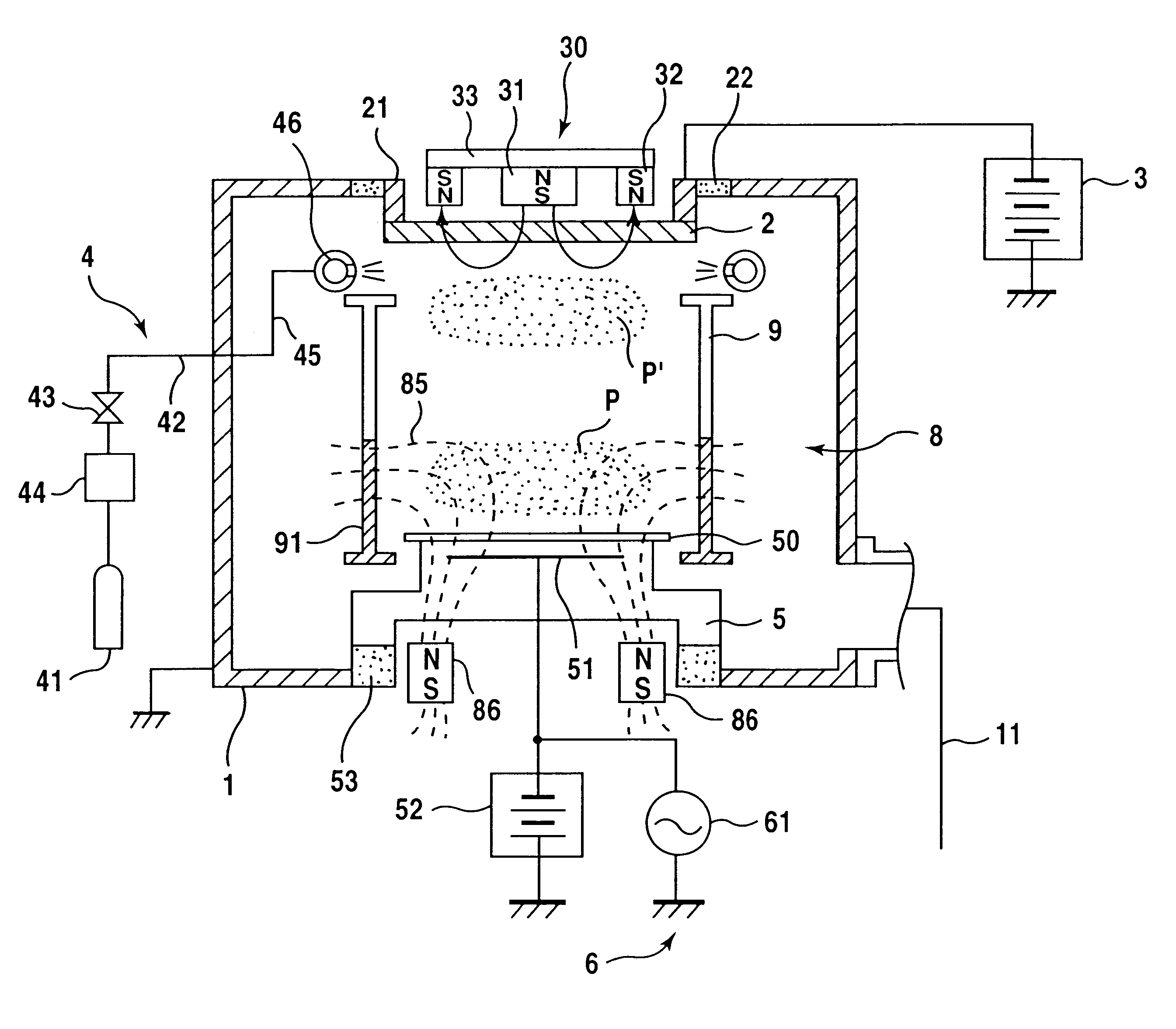
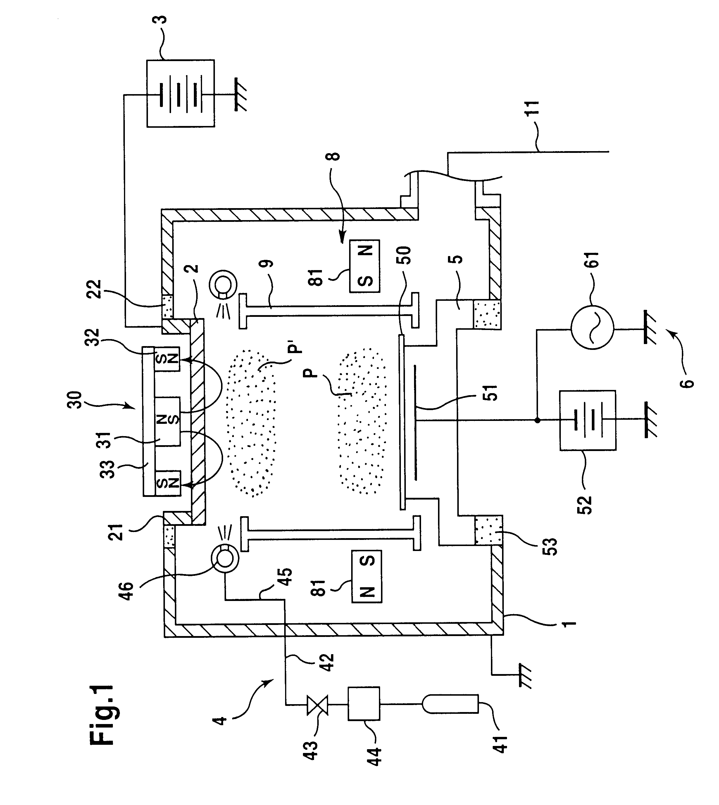
FIG. 1 shows a schematic front view of an ionization sputtering apparatus of the first mode. The apparatus shown in FIG. 1 is one for carrying out the ionization sputtering. The ionization sputtering is the method to make sputtered particles incident vertically to a hole on a substrate by ionizing sputtered particles and utilizing an effect of such ionized sputtered particles. The ionization sputtering brings much higher bottom coverage than the collimate sputtering and the LPLD sputtering.

Specifically, the apparatus of the first mode comprises a sputter chamber 1 having a pumping system 11, target 2 provided in sputter chamber 1, sputter source 3 for causing a sputter discharge on target 2, gas introduction means 4 for introducing a gas into sputter chamber 1, ionization means 6 for ionizing sputtered particles from target 2, a holder 5 for holding a substrate 50 at a place where ionizes sputtered particles arrive, and, ...


PUM

PropertyMeasurementUnit
Pressureaaaaaaaaaa
Pressureaaaaaaaaaa
Energyaaaaaaaaaa

Abstract

This invention discloses ionization sputtering apparatuses which have a function for ionizing sputtered particles. Those apparatuses comprise an ionization means for ionizing sputtered particles from a target. The ionization means generates a plasma by applying radio frequency energy with plasma generation gas at an ionization space between the target and a holder holding a substrate. An disclosed apparatus comprises a magnetic device preventing the plasma from diffusing from the ionization space. Another disclosed apparatus comprises a magnetic device which orients the ionized sputtered particles toward the substrate.

Description

BACK GROUND OF THE INVENTION1. Field of the InventionThis invention relates to a sputtering apparatus used for fabrication of various kinds of semiconductor devices, especially to an ionization sputtering apparatus which has a function for ionizing sputtered particles.2. Description of Prior ArtIn fabrication of semiconductor devices, sputtering process is widely utilized for depositions of many kinds of films such as wiring metal films and barrier films preventing cross-diffusion of dissimilar layers. In various properties of sputtering apparatuses, high step coverage onto a hole formed on a substrate has been more significant recently.Specifically, in the structure of CMOS-FET (complementary metal-oxide-semiconductor field effect transistor), which is broadly used in DRAM (dynamic random access memory), a barrier film is deposited onto a contact hole formed above a channel so that the cross-contamination of contact metal and the channel material. In multi-layer wiring structures, ...

Claims


Application Information

Patent Timeline
IPC IPC(8): C23C14/35H01J37/32H01J37/34C23C14/34C23C14/46H01L21/203H01L21/285
CPCC23C14/345C23C14/35H01J37/3405H01J37/3266C23C14/351C23C14/34
Inventor KOBAYASHI, MASAHIKOSAHASE, HAJIMETAKAHASHI, NOBUYUKI
Owner ANELVA CORP
Why Eureka
Try Eureka