Injection seeded F2 lithography laser

a lithography laser and injection seed technology, applied in the field of injection seeded f2 lithography lasers, can solve the problems of excessive wear and occasional failure of blower bearings, large and complex laser systems composed of two separate lasers, and limited commercial applications of two laser systems

Inactive Publication Date: 2002-04-09
CYMER INC
View PDF5 Cites 100 Cited by
  • Summary
  • Abstract
  • Description
  • Claims
  • Application Information

AI Technical Summary

Problems solved by technology

One problem experienced with these prior-art lasers has been excessive wear and occasional failure of blower bearings.
Laser systems comprised of two separate lasers tend to be substantially more expensive, larger and more complicated than comparable single laser systems.
Therefore, commercial applications of two laser systems has been limited.
The system shown in FIG. 3A has not been considered suitable for high pulse rate laser because debris from the upstream discharge interferes with the downstream discharge.
The authors indicate that an attempt to operate at 1000 Hz would lead to turbulent flow which is not desirable for generation of a high quality beam.
The system shown in FIG. 3C has not been considered suitable for high pulse rate lasers because splitting of the flow reduces the velocity of the gas between the electrodes by about 50% as compared to a single set of electrodes on the system shown in FIG. 3A.
The system shown in FIG. 3B has not been considered satisfactory for high pulse rate lasers because the blower circulation is axial rather than tangential as shown in FIG. 3.
A problem with the F.sub.2 laser and this line for lithography purposes (as compared with the KrF and ArF lasers) is that the line is not narrow enough to satisfy focusing requirements and it is too narrow to provide desired tuning flexibility.
As stated in the Background section of this specification, debris from the upstream discharge could interfere with the downstream discharge.
This problem results from the fact that the index of refraction, n, (which is a measure of the phase velocity of the beam) near the edges of the gain medium is significantly higher than at the center of the gain medium.
This produces a distortion of the wave front entering the LNP.
This distortion in turn limits the ability of the LNP 15 to produce very

Method used


Image

  • Injection seeded F2 lithography laser
  • Injection seeded F2 lithography laser
  • Injection seeded F2 lithography laser

Examples


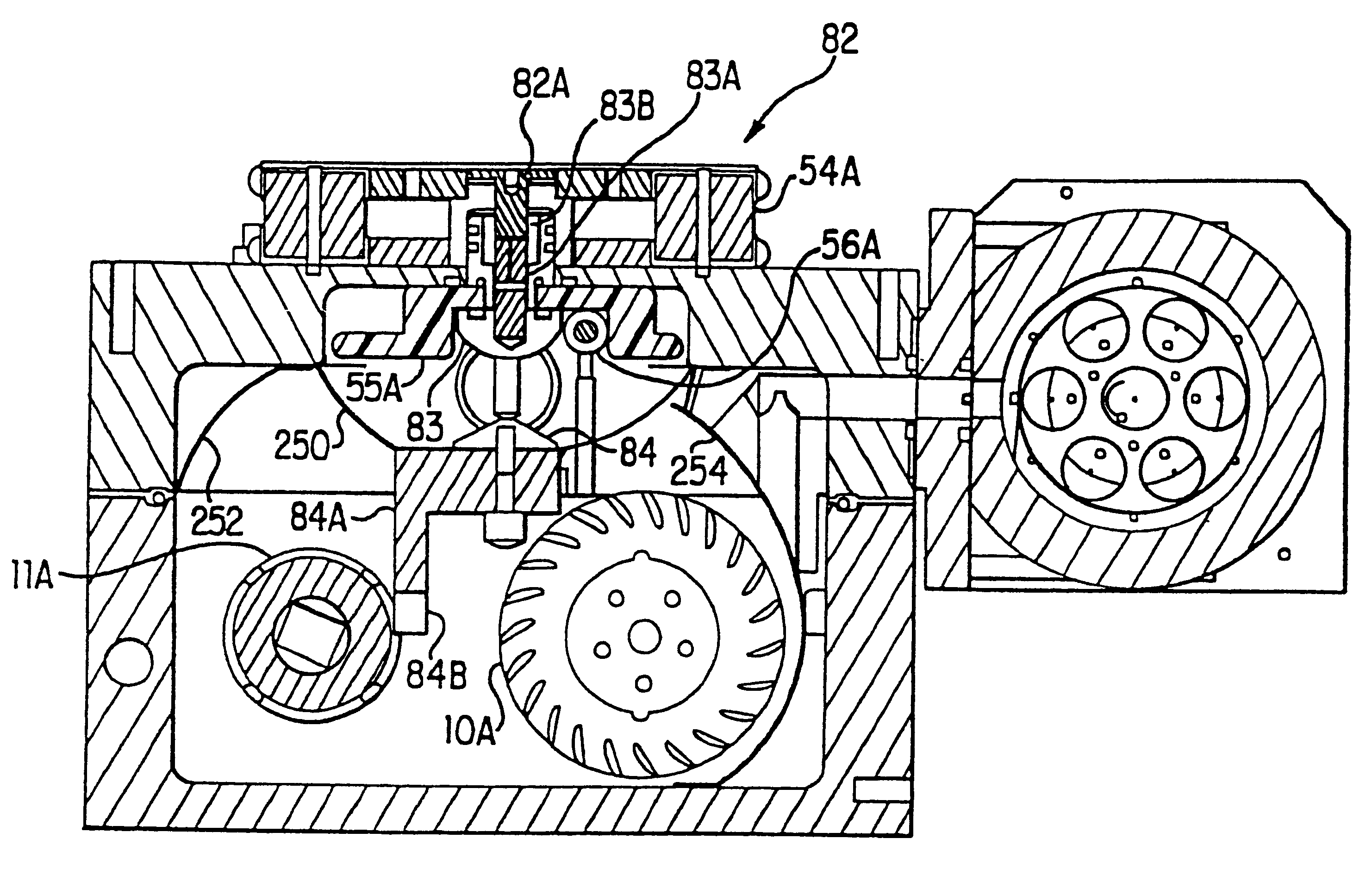
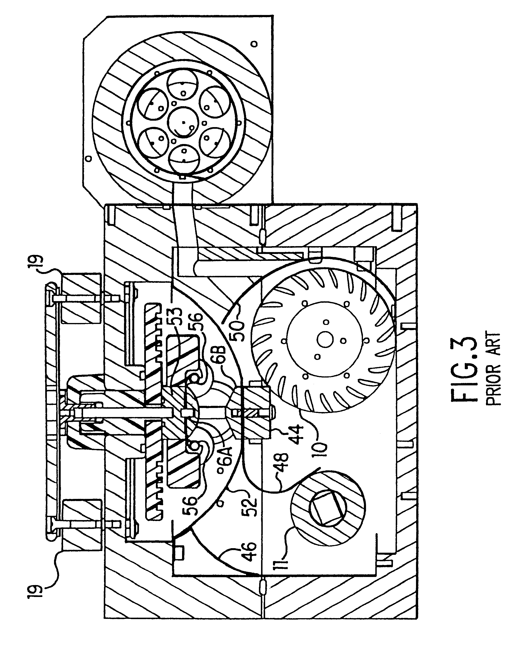
Embodiment Construction
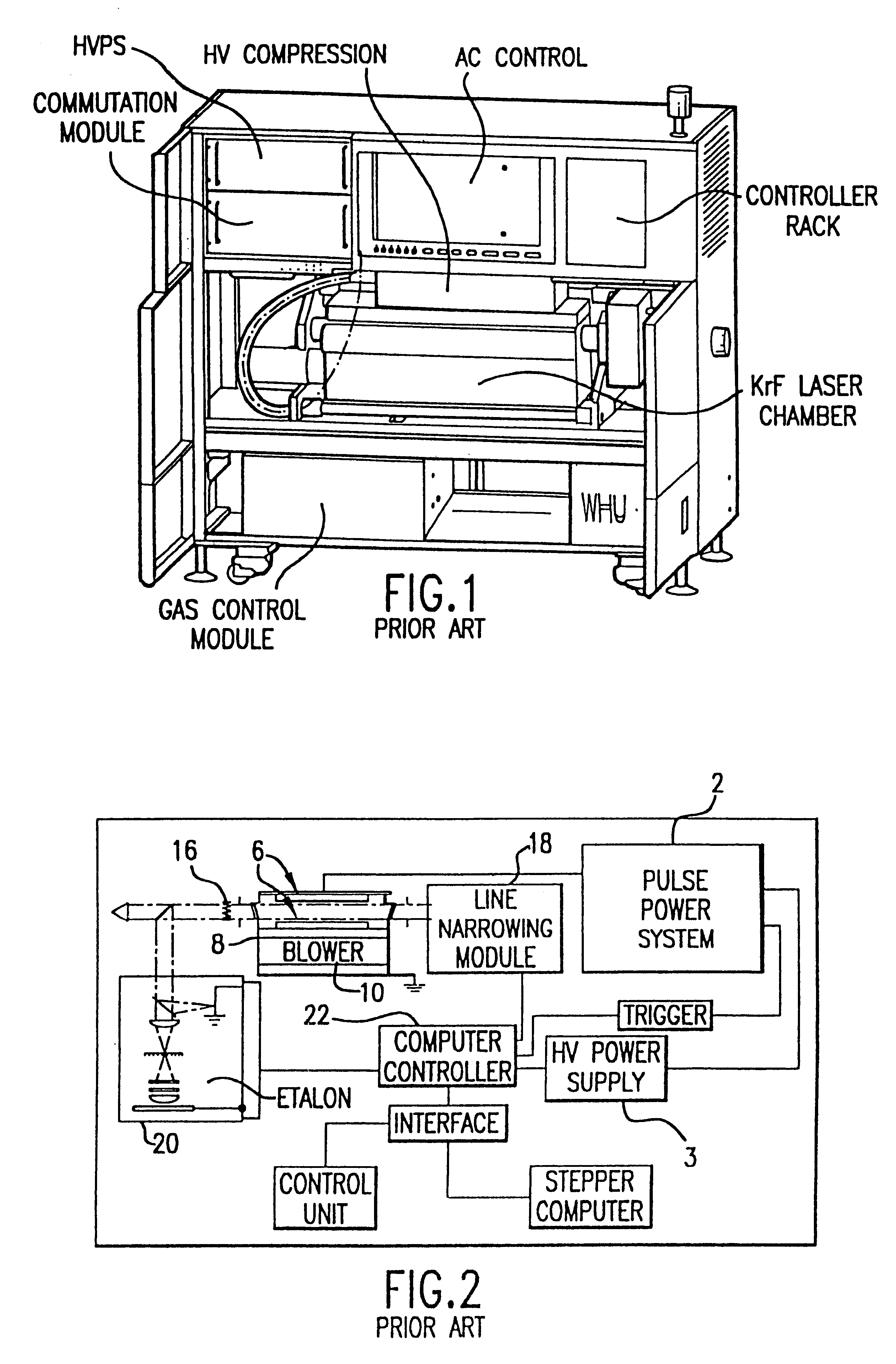
Power Supply

A more detailed circuit diagram of the power supply portion of the preferred embodiment is shown in FIG. 8C. As indicated in FIG. 8C, rectifier 22 is a 6 pulse phase controlled rectifier with a plus 150 v to -150V DC output. Inverter 24 is actually three invertors 24A, 24B and 24C. Invertors 24B and 24C are turned off when the voltage on 8.1 .mu.F Co charging capacitor 42 is 50 volts less than the command voltage and inverter 24A is turned off when the voltage on Co 42 slightly exceeds the command voltage. This procedure reduces the charge rate near the end of the charge. Step up transformers 26A, 26B and 26C are each rated at 7 kw and transform the voltage to 1200 volt AC.

Three bridge rectifier circuits 30A, 30B and 30C are shown. The HV power supply control board 21 converts a 12 bit digital command to an analog signal and compares it with a feedback signal 45 from Co voltage monitor 44. When the feedback voltage exceeds the command voltage, inverter 24A is turned off ...


PUM


Abstract

A tunable injection seeded very narrow band F2 lithography laser. The laser combines modular design features of prior art long life releasable lithography lasers with special F2 line narrowing and tuning techniques applied to a seed beam operated in a first gain medium which beam is used to stimulate narrow band lasing in a second gain medium to produce a very narrow band laser beam useful for integrated circuit lithography.

Description

Prior Art Lithography LasersKrF excimer lasers are the state of the art light source for integrated circuit lithography. One such laser is described in U.S. Pat. No. 4,959,340 issued Sep. 25, 1990. The lasers operate at wavelengths of about 248 nm. With the KrF laser integrated circuits with dimensions as small as 180 nm can be produced. Finer dimensions can be provided with ArF lasers which operate at about 193 nm or F.sub.2 lasers which operate at about 157 nm.These lasers, the KrF laser, the ArF laser and the F.sub.2 lasers, are very similar, in fact the same basic equipment used to make a KrF laser can be used to produce an ArF laser or an F.sub.2 laser merely by changing the gas concentration and modifying the controls and instrumentation to accommodate the slightly different wavelength.Control of lithography lasers and other lithography equipment require laser pulse energy monitors sensitive to the UV light produced by these lasers. The standard prior art detectors used for mo...

Claims


Application Information

Patent Timeline
IPC IPC(8): G03F7/20H01S3/23H01S3/14H01S3/036H01S3/225H01L21/027H01S3/038H01S3/097H01S3/134
CPCG03F7/70025G03F7/70041G03F7/70483G03F7/70575H01S3/2366H01S3/225H01S3/2308H01S3/2333H01S3/036
Inventor ONKELS, ECKEHARD D.DAS, PALASH P.DUFFEY, THOMAS P.SANDSTROM, RICHARD L.ERSHOV, ALEXANDER I.PARTLO, WILLIAM N.
Owner CYMER INC
Why Eureka
Try Eureka