Color cathode ray tube for reducing landing drift of electron beams on phosphor layers

a color cathode ray tube and electron beam technology, applied in the direction of cathode ray tubes/electron beam tubes, electric discharge tubes, electrical apparatus, etc., can solve the problems of color purity deterioration, color purity deterioration over a large area of the screen, color purity localization deterioration, etc., to reduce the landing drift of electron beams and difficult to cause color purity deterioration

Inactive Publication Date: 2002-05-07
KK TOSHIBA
View PDF21 Cites 9 Cited by
  • Summary
  • Abstract
  • Description
  • Claims
  • Application Information

AI Technical Summary

Benefits of technology

The present invention has been made in view of the above problem, and has an object of providing a color cathode ray tube which is capable of redu

Problems solved by technology

Consequently, the distance between the inner surface of the effective portion and the main surface of the mask body exceeds a tolerable value, and landing of electron beams onto the three-color phosphor layers is displaced thereby deteriorating color purity.
For example, when a high-luminance image is displayed on the entire screen, deterioration of color purity occurs over a large area of the screen.
When a high-luminance image is displayed locally, localized doming of the shadow mask occurs and landing positions are greatly drifted in a short time period, resulting in localized deterioration of color purity.
However, in the technique (a) of providing a graphite layer on the surface of a main surface portion of the mask body, adherence of the graphite layer is deteriorated by a heat treatment repeated in steps of manufacturing a color cathode ray tube, so that the graphite layer easily peels off by a vibration applied to the color cathode ray tube.
Small fragments of the l

Method used


Image

  • Color cathode ray tube for reducing landing drift of electron beams on phosphor layers
  • Color cathode ray tube for reducing landing drift of electron beams on phosphor layers
  • Color cathode ray tube for reducing landing drift of electron beams on phosphor layers

Examples


Embodiment Construction

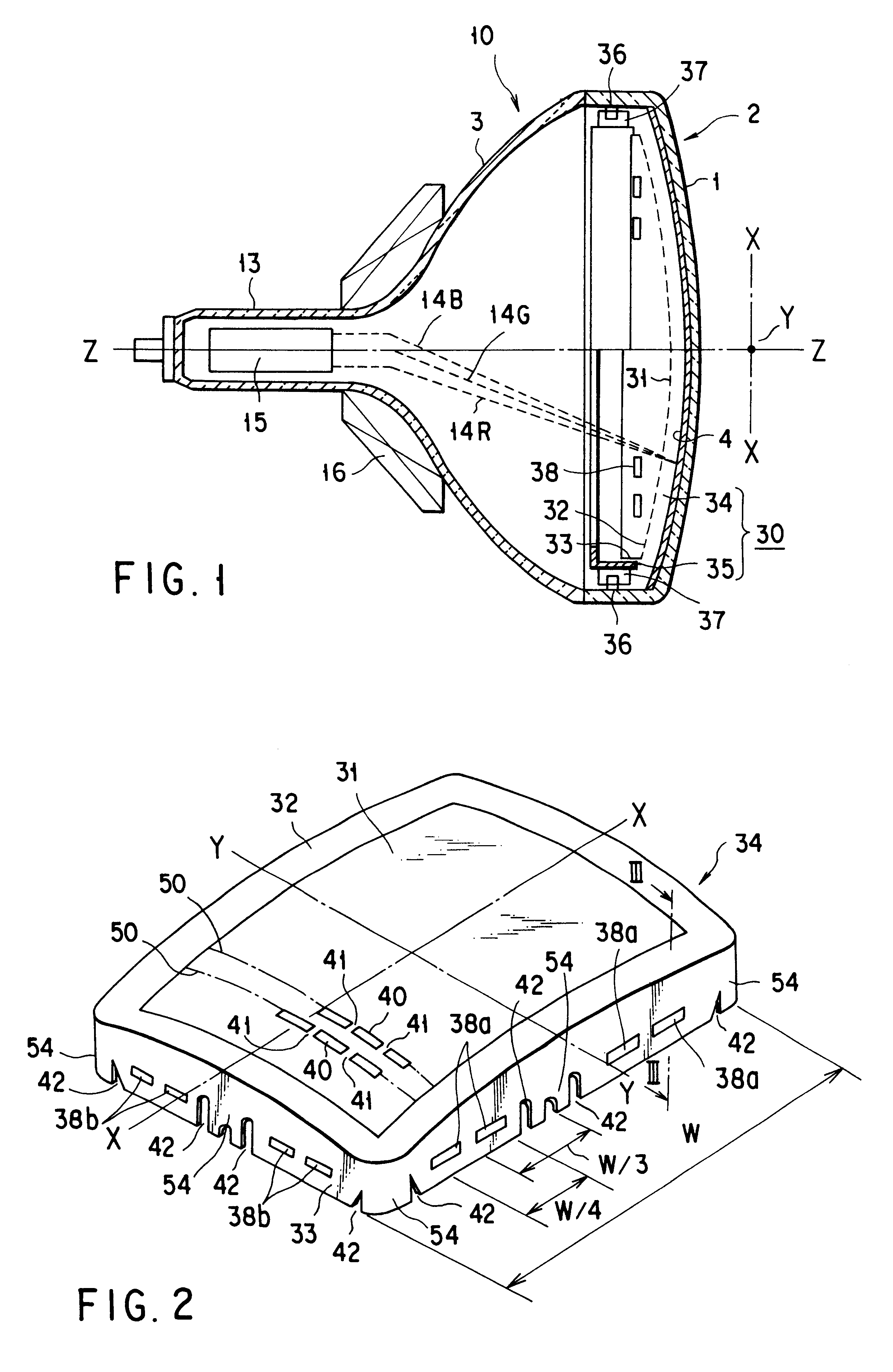
In the following, a color cathode ray tube according to an embodiment of the present invention will be described in detail with reference to the drawings.

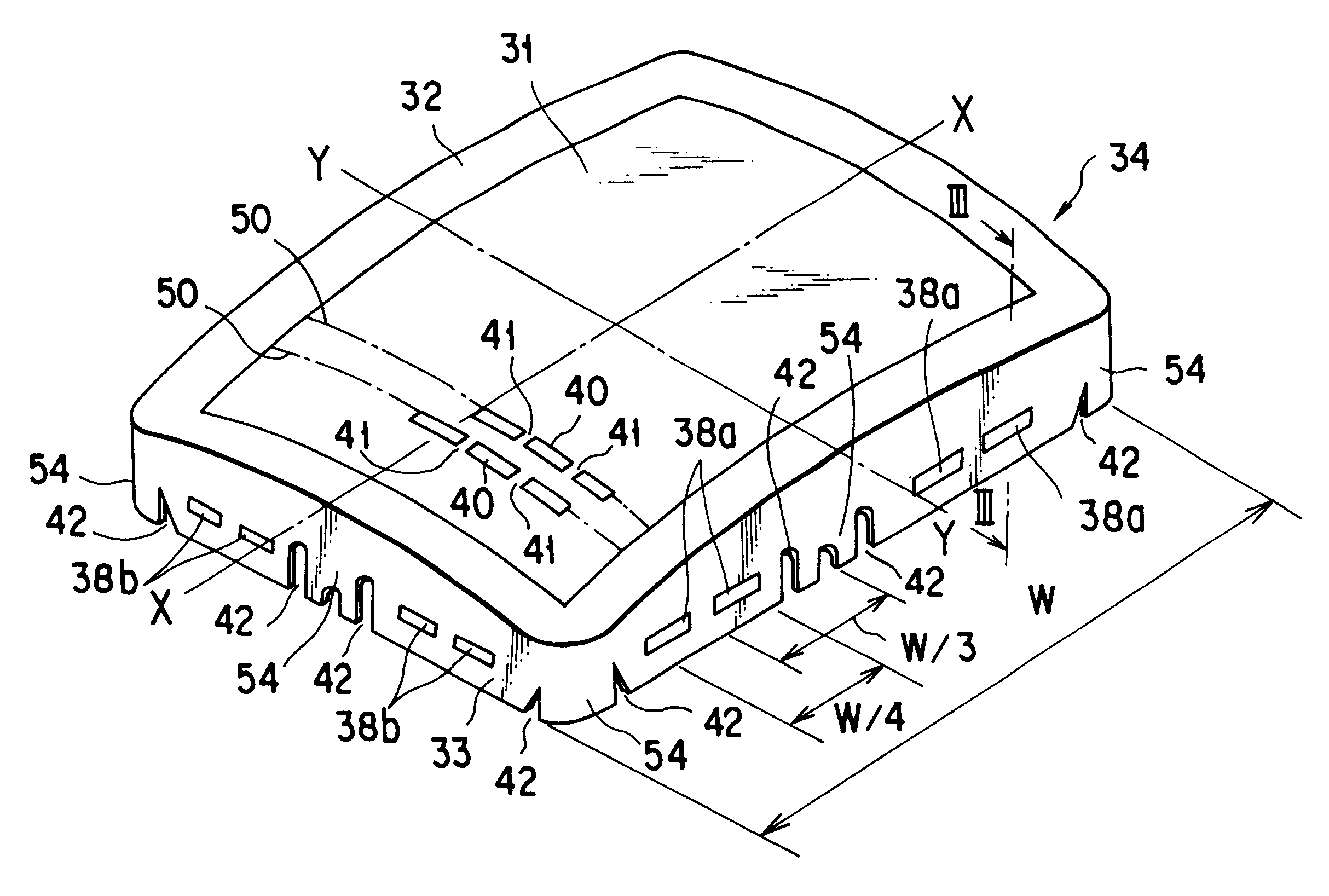
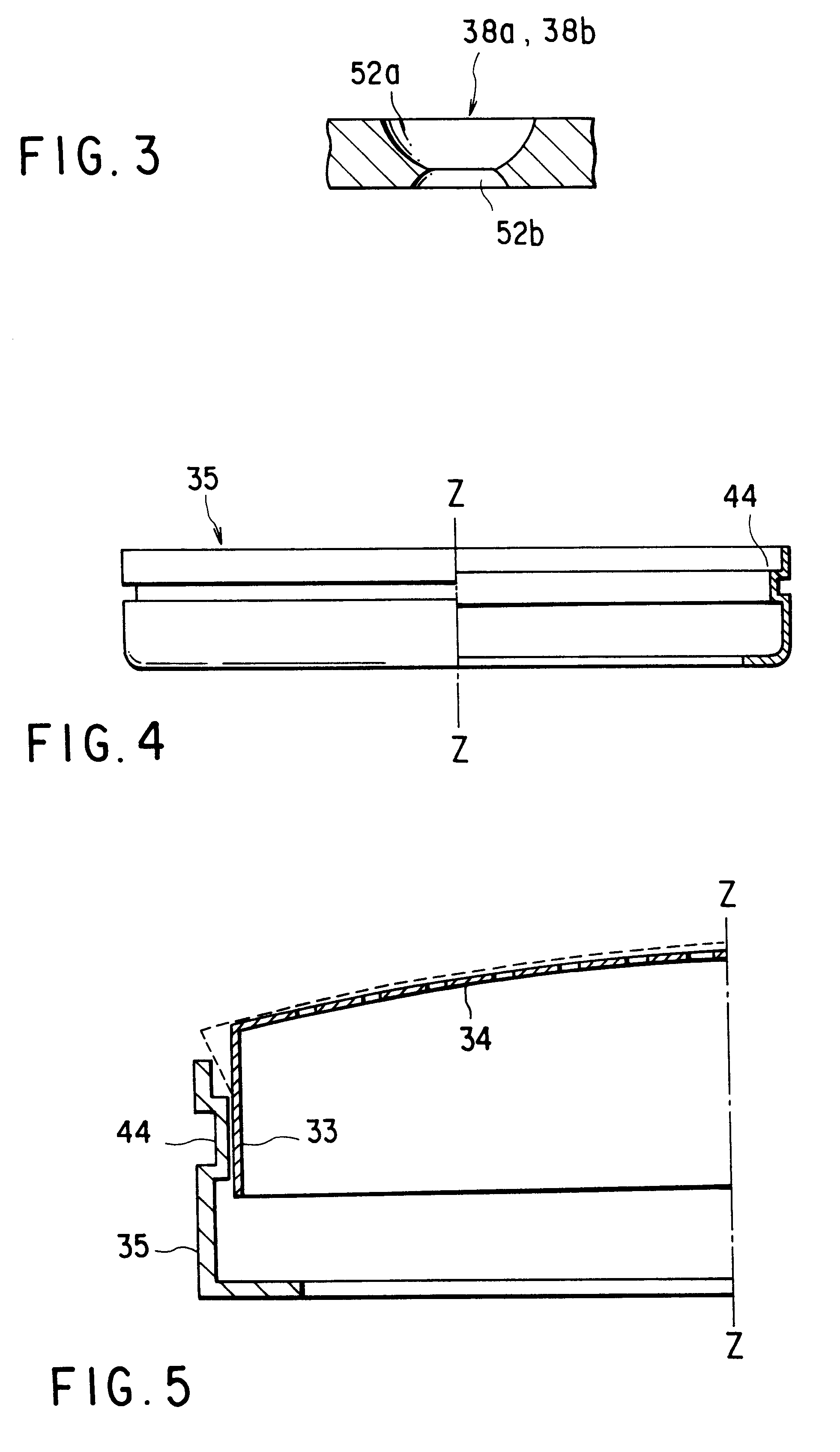
As shown in FIG. 1, a color cathode ray tube comprises a vacuum envelope 10 which includes a face panel 2 having a substantially rectangular effective surface 1 in form of a curved surface, and a funnel 3 connected with the face panel 2. A phosphor screen 4 made of phosphor layers of three colors which respectively radiate in blue, green, and red is formed on the inner surface of the effective portion 1 of the face panel 2. Inside the phosphor screen 4, a substantially rectangular shadow mask 30 described later is provided with a predetermined distance maintained from the face panel. An electron gun 15 which emits three electron beams 14B, 14G, and 14R is provided in a neck 13 of the funnel 3.

Further, in the color cathode ray tube, the three electron beams 14B, 14G, and 14R emitted from the electron gun 15 are deflected by a magnet...


PUM


Abstract

A main body 34 of a shadow mask is opposed to a phosphor screen and is formed in a substantially rectangular shape. The main body 34 has a main surface portion 31 where a number of electron beam apertures are formed, and a skirt portion 33 provided around the main surface portion with a non-aperture portion 32 interposed between the skirt portion and the main surface portion. A plurality of rectangular openings 38a extending in the long axis direction (or X-direction) of the mask body are formed at the skirt portion. Concave portions 47 extending in the long axis direction (X-direction) of the mask body are formed at the non-aperture portion. The openings and concave portions are provided within a range of about ¼ of the length W of the mask body in the long axis direction, with respect to a center of the range defined at a position distant from the short axis Y by about ⅓ of the length W of the long axis direction of the mask body.

Description

The present invention relates to a color cathode ray and particularly to a color cathode ray tube which restricts a landing displacement of electron beams on a phosphor layer caused by thermal expansion of a shadow mask.In general, a color cathode ray tube comprises a vacuum envelope, which includes a face panel having a substantially rectangular effective portion in form of a curved surface, and a funnel connected with the face panel. A phosphor screen made of a three-color phosphor layer which radiates in blue, green, and red is formed on the effective portion of the face panel. A shadow mask is arranged inside the phosphor screen with a predetermined distance maintained from the face panel. The shadow mask comprises a substantially rectangular mask body and a substantially rectangular mask frame equipped at a peripheral portion of the mask body.The mask body comprises a main surface portion having a number of electron beam apertures formed in a predetermined array and made of a c...

Claims


Application Information

Patent Timeline
IPC IPC(8): H01J29/07
CPCH01J29/073H01J2229/0772H01J29/07
Inventor TANI, MUNECHIKAMURAI, TAKASHISAOTOME, ICHIROINOUE, MASATSUGU
Owner KK TOSHIBA
Why Eureka
Try Eureka