Deforming charge assembly and method of making same

a charge assembly and charge technology, applied in the direction of weapons, ammunition loading, rocket motors, etc., can solve the problems of high temperature of loaded charge assemblies, extreme hazards, and fuel spread over flight decks, so as to achieve efficient mass production, efficiently explosive loading, and duplicate the performance characteristics of detasheets

Inactive Publication Date: 2002-05-14
THE GOVERNMENT OF THE UNITED STATES OF AMERICA AS REPRESENTED BY THE SEC OF THE NAVY NAVAL RES LAB WASHINGTON
View PDF19 Cites 17 Cited by
  • Summary
  • Abstract
  • Description
  • Claims
  • Application Information

AI Technical Summary

Benefits of technology

An explosive, such as PBXW-128, is injection loaded into the annular cavities and is sized to duplicate the performance characteristics of Detasheet which resolves the problems inherent with separate pieces of Detasheet and barriers. The present invention provides a deforming charge assembly which may be efficiently mass produced and that may be efficiently explosively loaded by the extrusion process. A deforming charge assembly is also provided by the present invention having a graphite housing which aids in meeting Insensitive Munitions (IM) requirements. In addition to light weight and strength, graphite material is electrically conductive, thereby eliminating the electrostatic hazard often associated with composites and explosives.

Problems solved by technology

Ordinance items such as loaded charge assemblies, for example those used in rocket motors, warheads and bombs, present an extreme hazard in the event of "cook off" which is defined for purposes of the subject application as detonation or deflagration of the main explosive charge of the item due to an accidental fire.
The transportation and storage of charge assemblies, loaded with an explosive, frequently requires placing them in environments which have a high probability of being in the proximity of open flames.
If accidental rupture of the fuel tank occurs, fuel spreads over the flight deck.
A fire that results upon ignition of the spilled fuel can subject the loaded charge assemblies to high temperatures along with a high risk of ignition of the explosive material in the charge assemblies.
The rapid internal pressure buildup in the loaded charge assemblies will result in case rupture and explosion with catastrophic results, including costly equipment losses and potential loss of life.
Such a charge assembly design renders the loaded charge assembly incapable of sustaining sufficient internal pressure to destructively detonate the charge assembly.
More sensitive Detasheet was available and could be used to complete development, but it was too sensitive for tactical applications.
Also, when producibility and depot maintenance were considered, the use of discrete strips of Detasheet with barriers between them was not an acceptable design.

Method used


Image

  • Deforming charge assembly and method of making same
  • Deforming charge assembly and method of making same
  • Deforming charge assembly and method of making same

Examples


Embodiment Construction

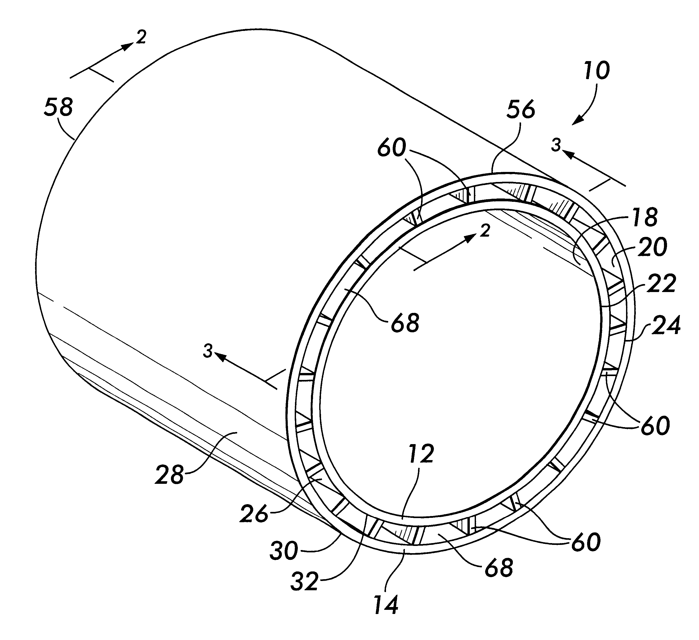
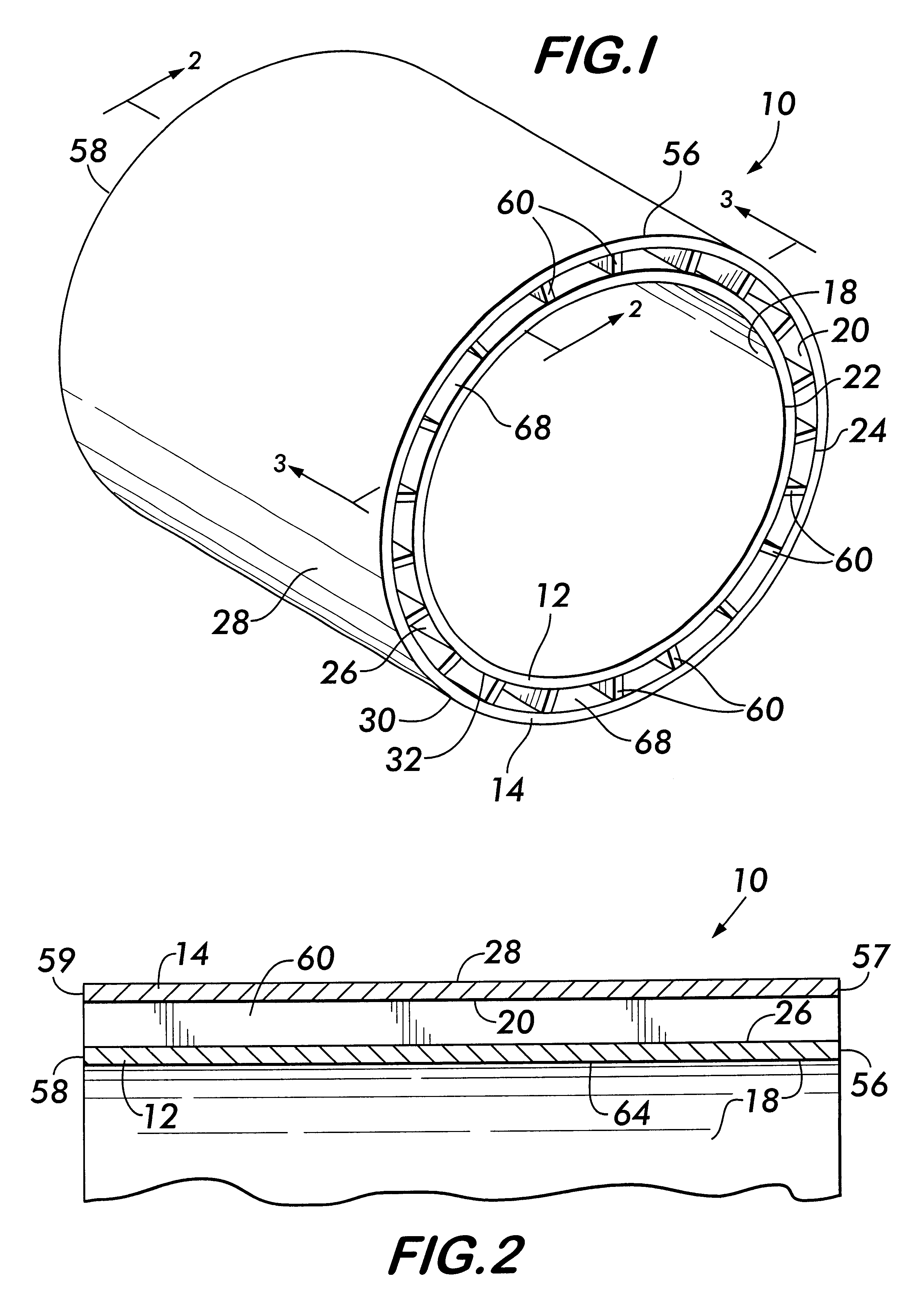
The present invention provides a deforming charge assembly 10 which has an inner and an outer cylinder 12, 14 respectively, formed from carbon fiber 16 as seen in FIGS. 1-4. Each of the inner and outer cylinders 12, 14 have an inner circumference surface 18, 20 respectively having an inner diameter 22, 24 respectively, an outer circumference surface 26, 28 respectively having an outer diameter 30, 32 respectively. The inner diameter 24 of the outer cylinder 14 is greater than the outer diameter 30 of the inner cylinder 12 and in a preferred design is about 0.57 inches greater.

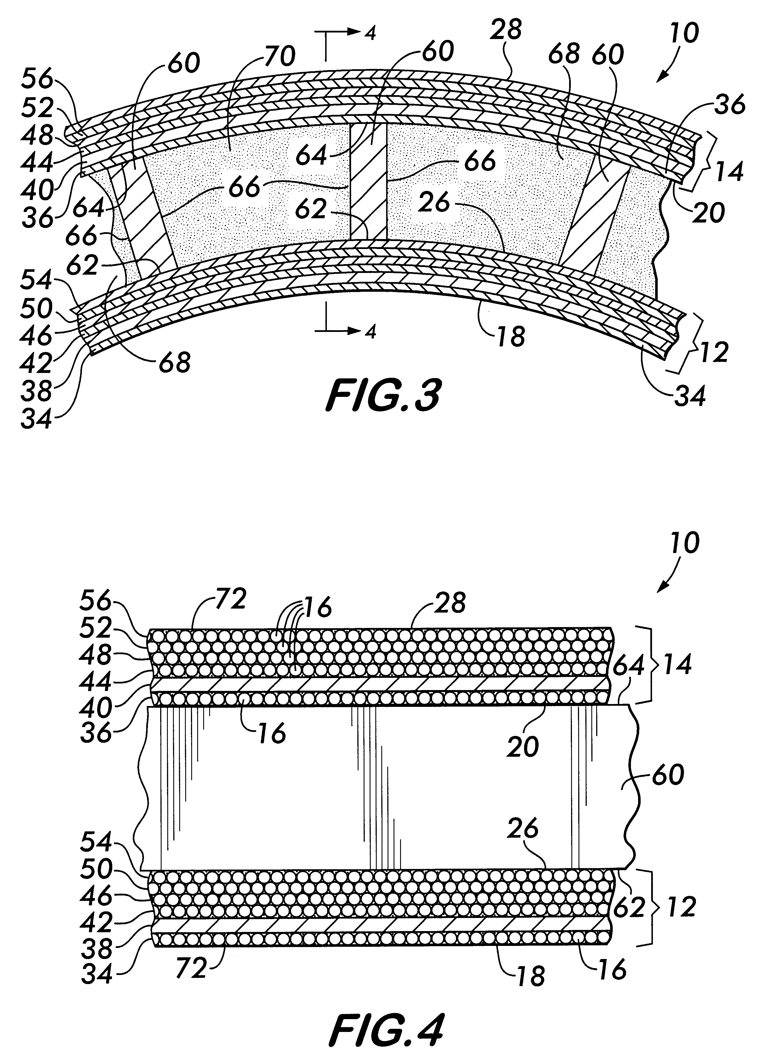
Each of the inner and outer cylinders 12, 14 have a first layer 34, 36 respectively of circumferentially wound carbon fiber 16, a second layer of 38, 40 of unidirectional carbon fiber sheet and four outer layers 42, 44, 46, 48, 50, 52, and 54, 56 respectively of carbon fibers 16 circumferentially wrapped around the second layer 38, 40. The layers 34, 38, 42, 46, 50 and 54 extend between the ends 56, 58 of the i...


PUM

PropertyMeasurementUnit
thickaaaaaaaaaa
thicknessaaaaaaaaaa
inner diameteraaaaaaaaaa

Abstract

A deforming charge assembly is provided which has an inner and an outer cylinder formed from carbon fiber. Each of the inner and outer cylinders have an inner circumference surface having an inner diameter and an outer circumference surface having an outer diameter. The inner diameter of the outer cylinder is greater than the outer diameter of the inner cylinder. Each of the inner and outer cylinders have a first layer of circumferentially wound carbon fiber, a second layer of unidirectional carbon fiber sheet and a plurality of layers of carbon fibers circumferentially wrapped around the second layer. A plurality of sympathetic detonation barrier members are provided and have an inner surface in contact with the outer circumference surface of the inner cylinder and an outer surface in contact with the inner circumference surface of the outer cylinder.

Description

STATEMENT OF GOVERNMENT INTERESTThe invention described herein may be manufactured and used by or for the Government of the United States of America for governmental purposes without the payment of any royalties thereon or therefor.BACKGROUND OF INVENTIONThe present invention relates to a deforming charge assembly and method of making same and more particularly to a deforming charge assembly which reduces the danger of explosion by the charge assembly.Ordinance items such as loaded charge assemblies, for example those used in rocket motors, warheads and bombs, present an extreme hazard in the event of "cook off" which is defined for purposes of the subject application as detonation or deflagration of the main explosive charge of the item due to an accidental fire. The transportation and storage of charge assemblies, loaded with an explosive, frequently requires placing them in environments which have a high probability of being in the proximity of open flames. For example, loaded ch...

Claims


Application Information

Patent Timeline
Patent Type & Authority Patents(United States)
IPC IPC(8): C06B45/00F42B12/76F42B12/00
CPCF42B12/76C06B45/00
Inventor LANDMAN, CHAARLES W.GRIGSBY, JR., WILLIAM H.GRIPSHOVER, ROBERT J.HANNICK, JOHN W.
Owner THE GOVERNMENT OF THE UNITED STATES OF AMERICA AS REPRESENTED BY THE SEC OF THE NAVY NAVAL RES LAB WASHINGTON
Why Eureka
Try Eureka