Optical chemical/biochemical sensor

a technology of optical sensors and biological chemicals, applied in the direction of photometry, material testing goods, instruments, etc., can solve the problems of difficult or impossible evaluation, limited detection sensitivity, and insoluble in solvents

Inactive Publication Date: 2002-05-28
ZEPTOSENS
View PDF19 Cites 237 Cited by
  • Summary
  • Abstract
  • Description
  • Claims
  • Application Information

AI Technical Summary

Problems solved by technology

Smaller values should be avoided since otherwise, even with very small tolerances in the alignment or the evenness of the sensor, the light pointer will be excited in a counter direction, rendering the evaluation difficult or impossible.
In that case the detection sensitivity may be limited by the absorption of excitation light by the support material or even by the excitation of the support material's inherent luminescence, especially in the case of additional luminescence detection.
The sample may, however, also comprise constituents that are not soluble in the solvent, such as pigment particles, dispersants, and natural and synthetic oligomers or polymers.

Method used


Image

  • Optical chemical/biochemical sensor
  • Optical chemical/biochemical sensor
  • Optical chemical/biochemical sensor

Examples


Embodiment Construction
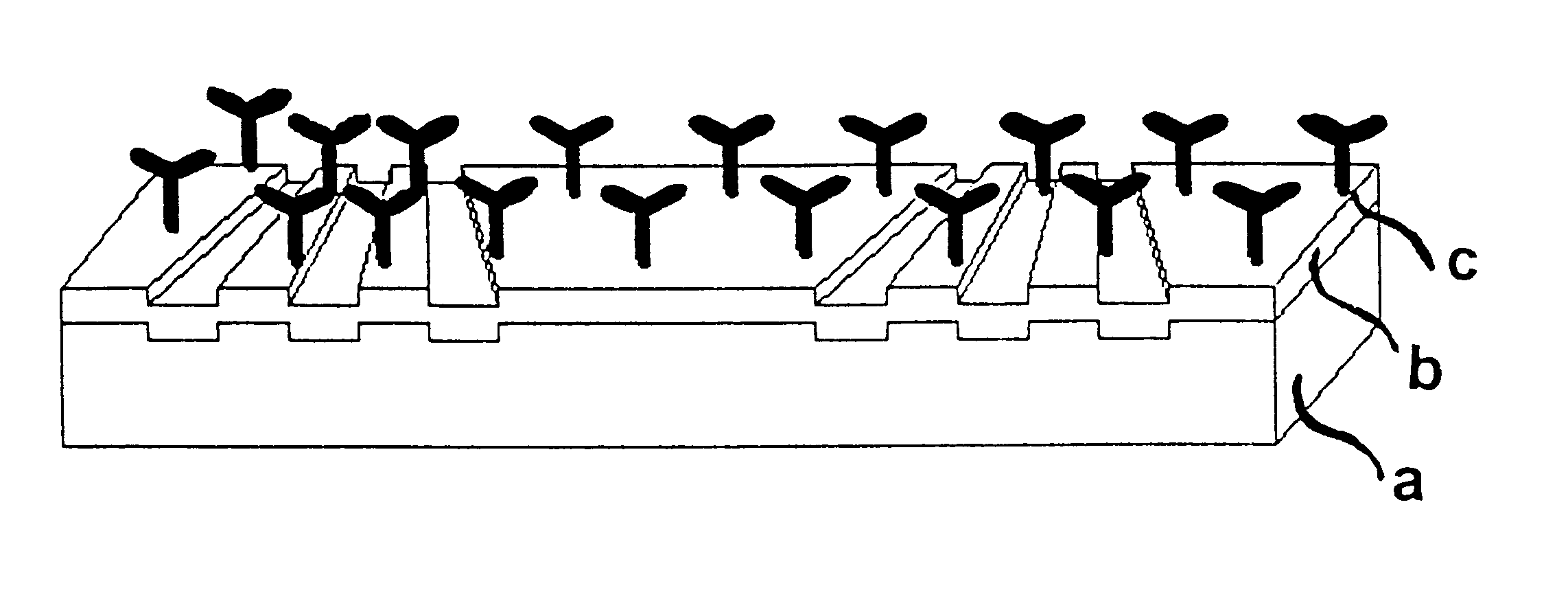
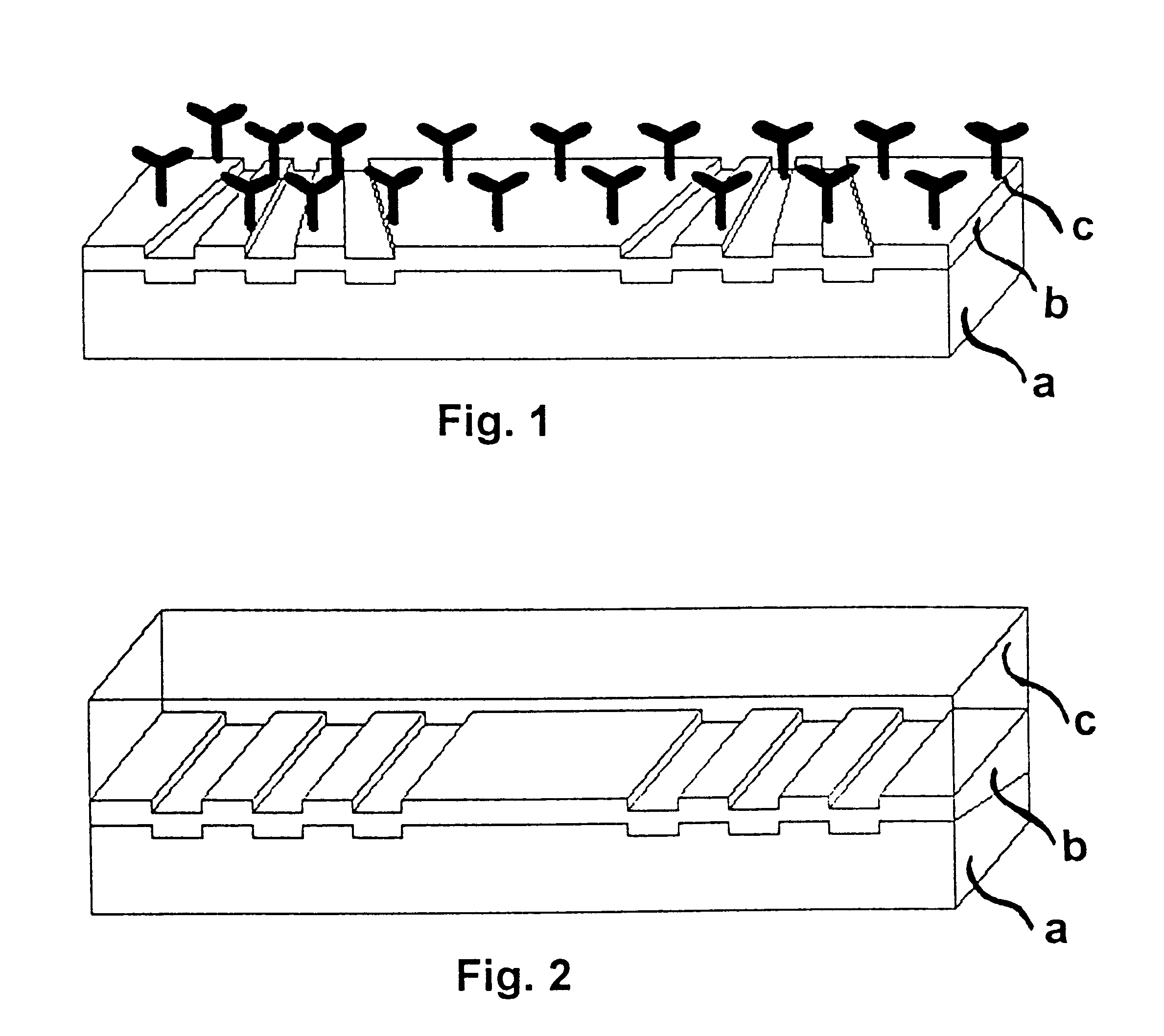
Optical system

The light source used is a helium-neon laser (.lambda.=632.8 nm, TM.sub.0 -mode, Uniphase, Manteca, USA), set using a projection system to a beam spot having a diameter in the sensor plane of 0.4 mm perpendicular to the lines of the coupling grating and 3 mm parallel to the grating lines.

Motorised adjusting units are used to set the coupling-in angle and to position the beam spot relative to the grating edge.

Linearly polarised light having TE or TM orientation, as desired, can be coupled in by means of rotatable polarising elements.

On the upper side of the sensor platform there is arranged a flow cell which is sealed with respect to the sensor by O-rings; the sample volume of this cell is approximately 20 .mu.l. Different solutions can be introduced into the cell by way of injection pumps and switch-over valves.

The detector used for detecting the position of the light pointer is a two-dimensional CCD camera (Sony XC-77CE) with 756.times.581 (horizontal.times.vertical) ...


PUM

PropertyMeasurementUnit
thicknessaaaaaaaaaa
angleaaaaaaaaaa
angleaaaaaaaaaa

Abstract

The invention relates to a planar ATR and evanescently exited luminescence optical sensor platform, consisting of a transducer and a recognition layer, wherein changes in the effective refractive index of the recognition layer are converted into a measurable variable in accordance with the integrated-optical light pointer principle. The invention relates also to the use of the method and to the method itself using the sensor platform, for example in label-free biosensory analysis.

Description

This application is a 371 application of PCT / EP97 / 04678 filed Aug. 27, 1997.1. Field of the InventionThe invention relates to a planar optical sensor platform, consisting of a transducer and a recognition layer, wherein changes in the effective refractive index of the recognition layer are converted into a measurable variable in accordance with the integrated-optical light pointer principle. The invention relates also to the use of the method and to the method itself using the sensor platform, for example in label-free biosensory analysis.2. Description of the Related ArtThe integrated-optical light pointer principle is described in WO 92 / 19976. It is based on the conversion of the change in the coupling angle, for coupling a light beam into a waveguide by means of a diffraction grating, into a position-dependent change in the signal, that is to say the coupling-in position, on the transducer. By means of the embodiments described below, the condition for coupling in a light beam co...

Claims


Application Information

Patent Timeline
Patent Type & Authority Patents(United States)
IPC IPC(8): G01N21/77G01N21/27G01N21/64G01N33/543
CPCG01N21/7743
Inventor DUVENECK, GERT LUDWIGDUBENDORFER, JURGKUNZ, RINO ERNSTKRAUS, GEROLF
Owner ZEPTOSENS
Why Eureka
Try Eureka