

Laser beam generating apparatus
a laser beam and generating apparatus technology, applied in the direction of instruments, semiconductor lasers, optical resonator shape and construction, etc., can solve the problems of steep drop in output, large power density, and heavy damage both on the surface and insid
- Summary
- Abstract
- Description
- Claims
- Application Information
AI Technical Summary
Problems solved by technology
Method used
Image

Examples
embodiment 2
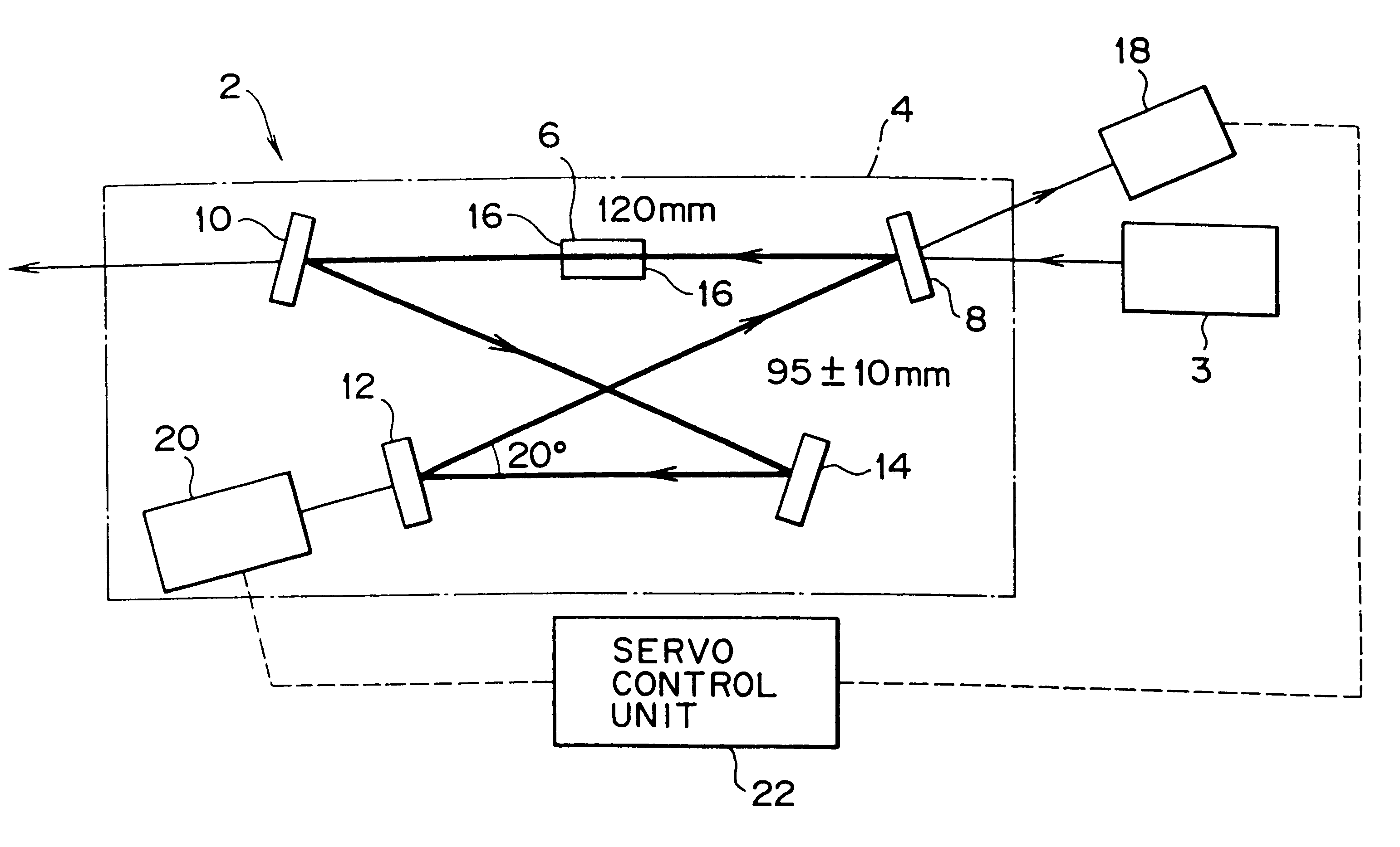
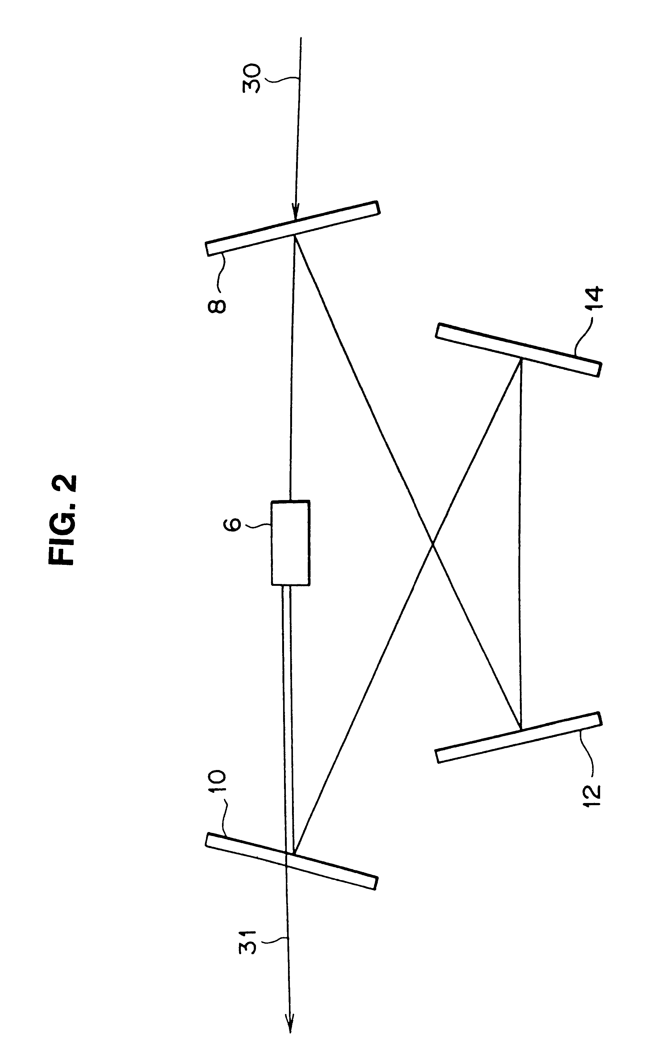
This embodiment, like Embodiment 1, represents an application of the invention to an optical system for ultraviolet beam generation having an external resonator section, described with reference to FIG. 2, i.e. a wavelength converting system wherein a nonlinear optical crystal is disposed in an external resonator. Herein, the inside of the external resonator shown in FIG. 2 was purged with air of 99.999% in purity, and wavelength conversion was carried out in a way similar to the above-described.
As a result, a similar effect to that of Embodiment 1 was achieved. Especially, UV power becomes stable, when 1% or more of the ambiance of optical component is oxygen.
embodiment 3
This embodiment, like Embodiment 1, represents an application of the invention to an optical system for ultraviolet beam generation having an external resonator section, described with reference to FIG. 2, i.e. a wavelength converting system wherein a nonlinear optical crystal is disposed in an external resonator. Herein, the inside of the external resonator shown in FIG. 2 was purged with a gas with a moisture content of 0.001%, and wavelength conversion was carried out in a way similar to the above-described.
As a result, a similar effect to that of Embodiment 1 was achieved.
embodiment 4
This embodiment, like Embodiment 1, represents an application of the invention to an optical system for ultraviolet beam generation having an external resonator section, described with reference to FIG. 2, i.e. a wavelength converting system wherein a nonlinear optical crystal is disposed in an external resonator, wherein the inside of the external resonator shown in FIG. 2 was purged with a gas with a hydrocarbon content of 0.001%, and wavelength conversion was carried out in a way similar to the above-described.
As a result, a similar effect to that of Embodiment 1 was achieved.
PUM
 Abstract
Description
Claims
Application Information