
System and method for providing a trap and patch function to low power, cost conscious, and space constrained applications

a software and patch function technology, applied in the field of system and method for providing a software trap and patch function to low power and space constrained applications, can solve the problems of prohibitively expensive scrap device, unfavorable product shipment, and bug or program error within pre-programmed cod

Inactive Publication Date: 2002-06-25
SKYWORKS SOLUTIONS INC
View PDF10 Cites 40 Cited by
  • Summary
  • Abstract
  • Description
  • Claims
  • Application Information

AI Technical Summary

Benefits of technology

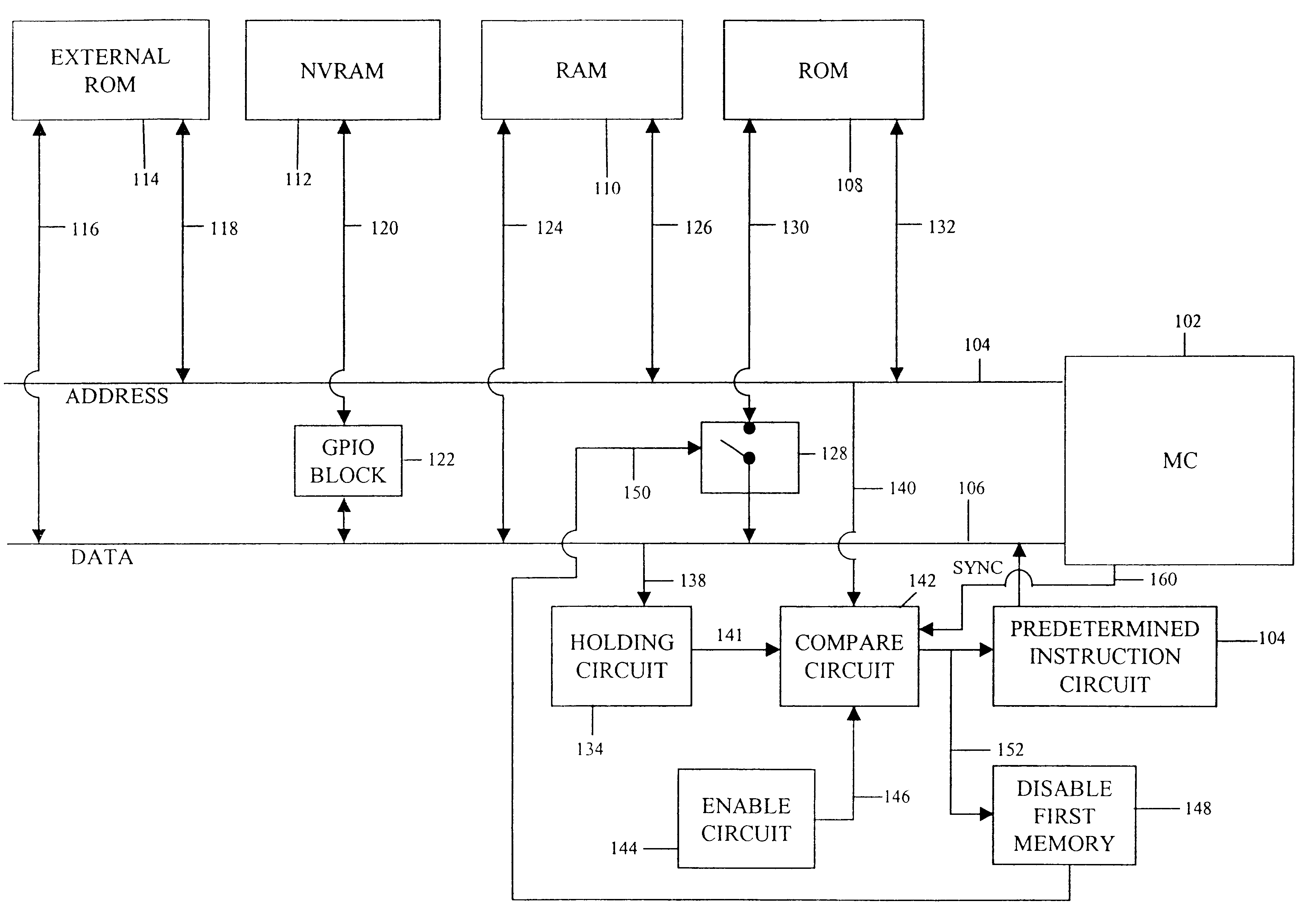
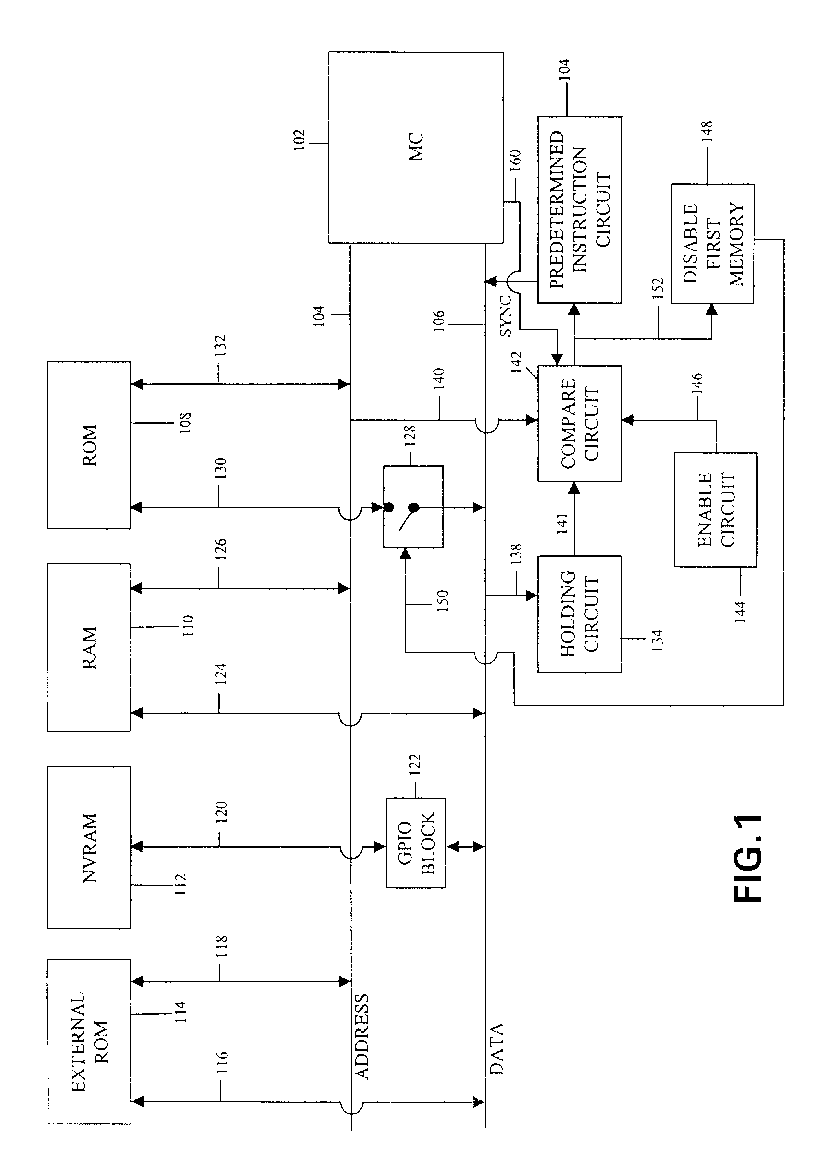
An advantage of the present invention is that it requires only the addition of combinational logic to the microprocessor for the purpose of placing a predetermined instruction on the data bus, rather than the sequential logic which characterizes conventional approaches. The result is an overall circuit design that consumes less power and requires less space and cost than the conventional approaches, and thus is more suitable for many consumer electronic devices.
Another advantage of one embodiment of the present invention is that, by distinguishing between an interrupt generated responsive to a trap condition, and a software interrupt generated upon the occurrence of a user-defined condition, the predetermined instruction, in this case, the software interrupt instruction, need not be dedicated to the function of generating an interrupt responsive to a trap condition, but can serve the additional purpose of generating a software interrupt.
Still another advantage of one embodiment of the present invention is that the software trap and patch function is implemented using a predetermined instruction that can be placed on the data bus in a single bus cycle. This eliminates the need for a state machine as required in conventional approaches to place a predetermined instruction on the data bus in multiple bus cycles.
Yet another advantage of one embodiment of the present invention is a software trap and patch system that does not require specialized circuitry to handle other interrupts, either hardware or software, that may occur during the trap and patch process.

Problems solved by technology

Thus, a problem occurs when it is discovered that a bug or program error exists within the pre-programmed code stored in the ROM of fabricated devices.
It is prohibitively expensive to scrap devices whenever a programming error is discovered, and it would unduly delay the shipment of the product if it were necessary to ship devices fabricated with the correct ROM code.
The problem with this approach is that, because of the complexity and size of the circuitry required to perform the trap and patch function, it is not particularly well-suited for low power, cost conscious and space constrained applications, such as wireless or cordless handsets.
The power consumed, cost, and space occupied by circuitry such as this will, in many cases, render this approach unsuitable for use in low power, cost conscious and space constrained applications, such as cordless or wireless handsets.
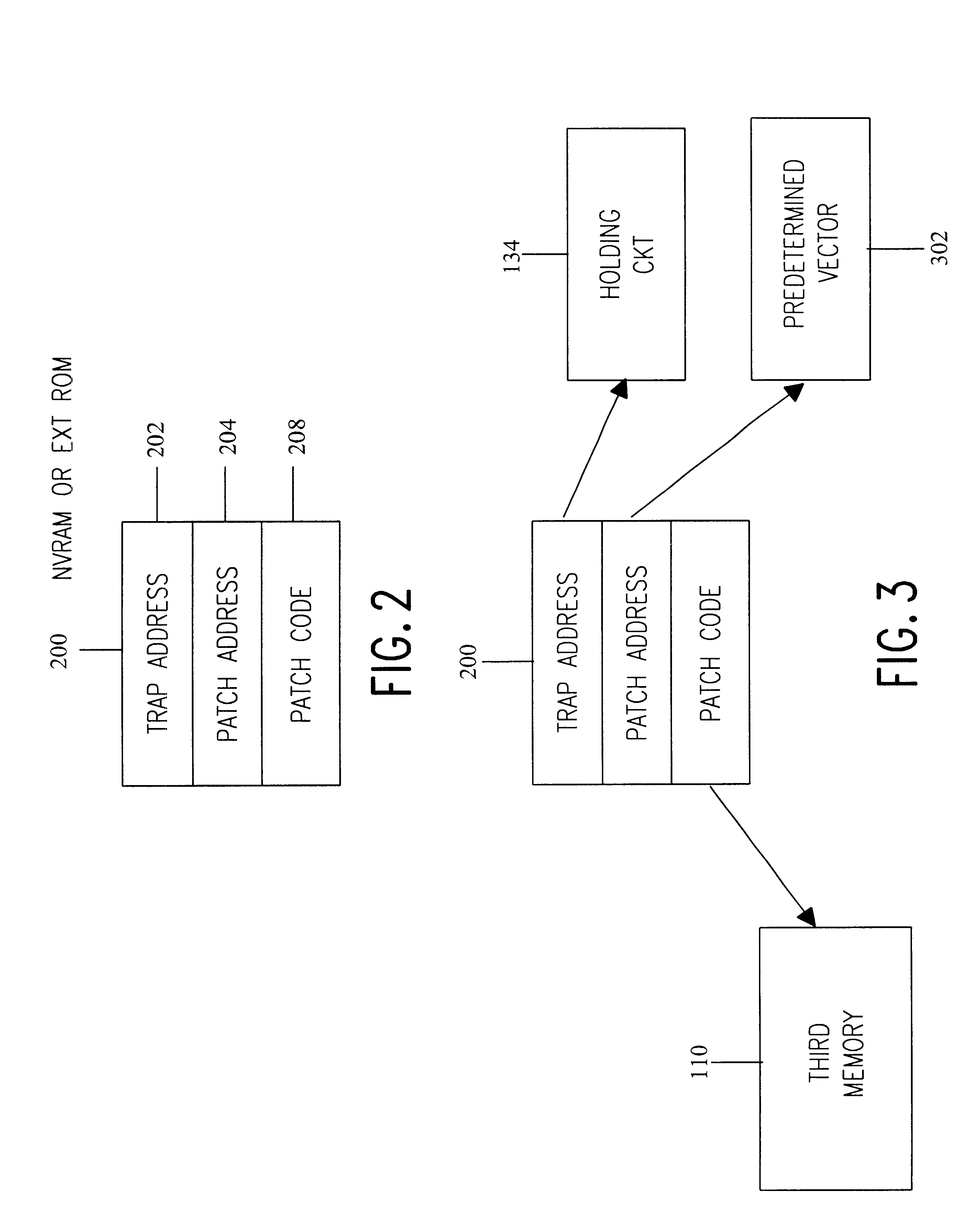
In particular, when a programming error is discovered in program code stored in a first memory, patch code is provided in a second memory accessible by the microprocessor.
In one implementation, since the cost / bit of the second memory is typically greater than that of the first memory, it is not generally economically feasible to replicate the entire program code, with the bug or error corrected, in the second memory.
Since a device such as this tends to be a relatively low-cost consumer product, it is impractical to scrap devices or recall the same from the field or from distribution in order to correct bugs in the program code.
This saves cost in terms of manufacturing expense, power consumption and space requirements.
Upon the conclusion of the execution of this patch code, it would not be desirable to restore the value of the accumulator that was stored on the stack in step 515 since that would interfere with the desired operation of the patch code.
Consequently, it is unnecessary to add specialized circuitry to perform this task.

Method used


Image

  • System and method for providing a trap and patch function to low power, cost conscious, and space constrained applications
  • System and method for providing a trap and patch function to low power, cost conscious, and space constrained applications
  • System and method for providing a trap and patch function to low power, cost conscious, and space constrained applications

Examples


Embodiment Construction

An implementation example of the subject invention will now be described. In this example, the microprocessor is a Rockwell MC19 CMOS 8-bit microprocessor, a microprocessor which is software compatible with the Rockwell 65C02 microprocessor. The architecture of the MC19 is illustrated in FIG. 6. As indicated, the MC19 has a 16 bit external address bus, identified by numerals 600a and 600b, with numeral 600a identifying the low byte of the address bus, and numeral 600b identifying the high byte of the address bus. The external data bus of the MC19 is an 8 bit bus, identified with numeral 601. The program counter of the MC19 is identified with numeral 603. As indicated, the program counter is divided into a high byte, designated PCH, and a low byte, designated PCL, to achieve compatibility with the internal data bus 606, which is 8 bits wide. That is, the PC is divided into upper and lower bytes to allow the contents of the PC to be accessible over the internal data bus through succes...


PUM


Abstract

A system and method for providing a software trap and patch function to low power, cost conscious, and space constrained applications. When a programming error in a first memory is discovered, a data structure comprising a trap address, patch code, and patch address are stored in a second memory. A power-on-reset process detects the presence of the data structure, and in response thereto, enables the trap and patch function. In operation, upon the occurrence of a trap condition, the first memory is disconnected from the data bus and a predetermined instruction circuit is activated. Upon activation thereof, the predetermined instruction circuit, which comprises solely combinational circuitry, places the op code of the predetermined instruction on the data bus. In one embodiment, in which the predetermined instruction is a software interrupt instruction, a predetermined bit of the PSR is placed in a defined state responsive to the occurrence of a trap condition. Upon execution of the software interrupt instruction, the processor executes an interrupt request service routine. There, the predetermined bit of the PSR is examined to see if it is in the predefined state. If so, and the interrupt was caused by a trap condition in contrast to a software interrupt, the service routine causes the processor to execute the patch code in place of the error-containing code. If not, signifying a hardware interrupt, another service routine is executed.

Description

1. Field of the InventionThe present invention relates to a system and method for providing a software trap and patch function, and more specifically, a software trap and patch function to low power and space constrained applications.2. Related ArtThe microprocessor is an integral part of many modern consumer electronic devices. The microprocessor, in combination with one or more software programs, provides many of the features and functions of the consumer electronic device. Such software programs are typically stored on the microprocessor device or as a standalone device in read only memory ("ROM") and installed during the manufacturing process.Programs that are stored in ROM cannot generally be altered. Thus, a problem occurs when it is discovered that a bug or program error exists within the pre-programmed code stored in the ROM of fabricated devices. It is prohibitively expensive to scrap devices whenever a programming error is discovered, and it would unduly delay the shipment...

Claims


Application Information

Patent Timeline
IPC IPC(8): G06F11/26G06F9/445G06F9/48
CPCG06F9/4812Y02B60/144G06F2209/481G06F8/665G06F8/654Y02D10/00
Inventor KOSCAL, MICHAEL E.BERGER, DOUGLAS M.
Owner SKYWORKS SOLUTIONS INC
Learn More