Separator for a high energy rechargeable lithium battery

a lithium battery and high energy technology, applied in the field of separation of high energy rechargeable lithium batteries, can solve the problems of high resistance of the severity of the problem with the above-mentioned high energy anodes is much greater, and the commercial success of lithium metal or lithium alloy batteries has eluded all but primary cells, so as to improve the conductivity and reduce the resistance

Inactive Publication Date: 2002-08-13
CELGARD LLC
View PDF7 Cites 421 Cited by
  • Summary
  • Abstract
  • Description
  • Claims
  • Application Information

AI Technical Summary

Benefits of technology

Referring to the figures, wherein like numerals indicate like elements, there is shown in FIG. 1 a lithium metal battery (or cell) 10. Lithium metal cell 10 comprises a lithium metal anode 12, a cathode 14, and a separator 16 disposed between anode 12 and cathode 14, all of which is packaged within a can 20. The illustrated cell 10 is a cylindrical cell or `jelly roll` cell, but the invention is not so limited. Other configurations, for example, prismatic cells, button cells, or polymer cells are also included. Additionally, not shown is the electrolyte. The electrolyte may be a liquid (organic or inorganic), or a gel (or polymer). The invention will be, for convenience, described with regard to a c ylindrical cell with a liquid organic electrolyte, but it is not so limited and may find use in other cell types (e.g. energy storage system, combined cell and capacitor) and configurations.

Problems solved by technology

The commercial success of lithium metal or lithium alloy batteries has eluded all but primary cells due to persistent safety problems.
The difficulties associated with the use of the foregoing anodes stem mainly from lithium dendrite growth that occurs after repetitive charge-discharge cycling.
(While dendrite growth is a potential problem with any lithium battery, the severity of the problem with the above-mentioned high energy anodes is much greater than with other lithium anodes (e.g. pure carbon intercalation anodes) as is well known in the art.)
Some shorting (i.e., a soft short), caused by very small dendrites, may only reduce the cycling efficiency of the battery.
Other shorting may result in thermal runaway of the lithium battery, a serious safety problem for lithium rechargeable battery.
The failure to control the dendrite growth from such anodes remains a problem, limiting the commercialization of cells with those anodes, particularly those cells with liquid organic electrolytes.

Method used


Image

  • Separator for a high energy rechargeable lithium battery
  • Separator for a high energy rechargeable lithium battery

Examples


Embodiment Construction

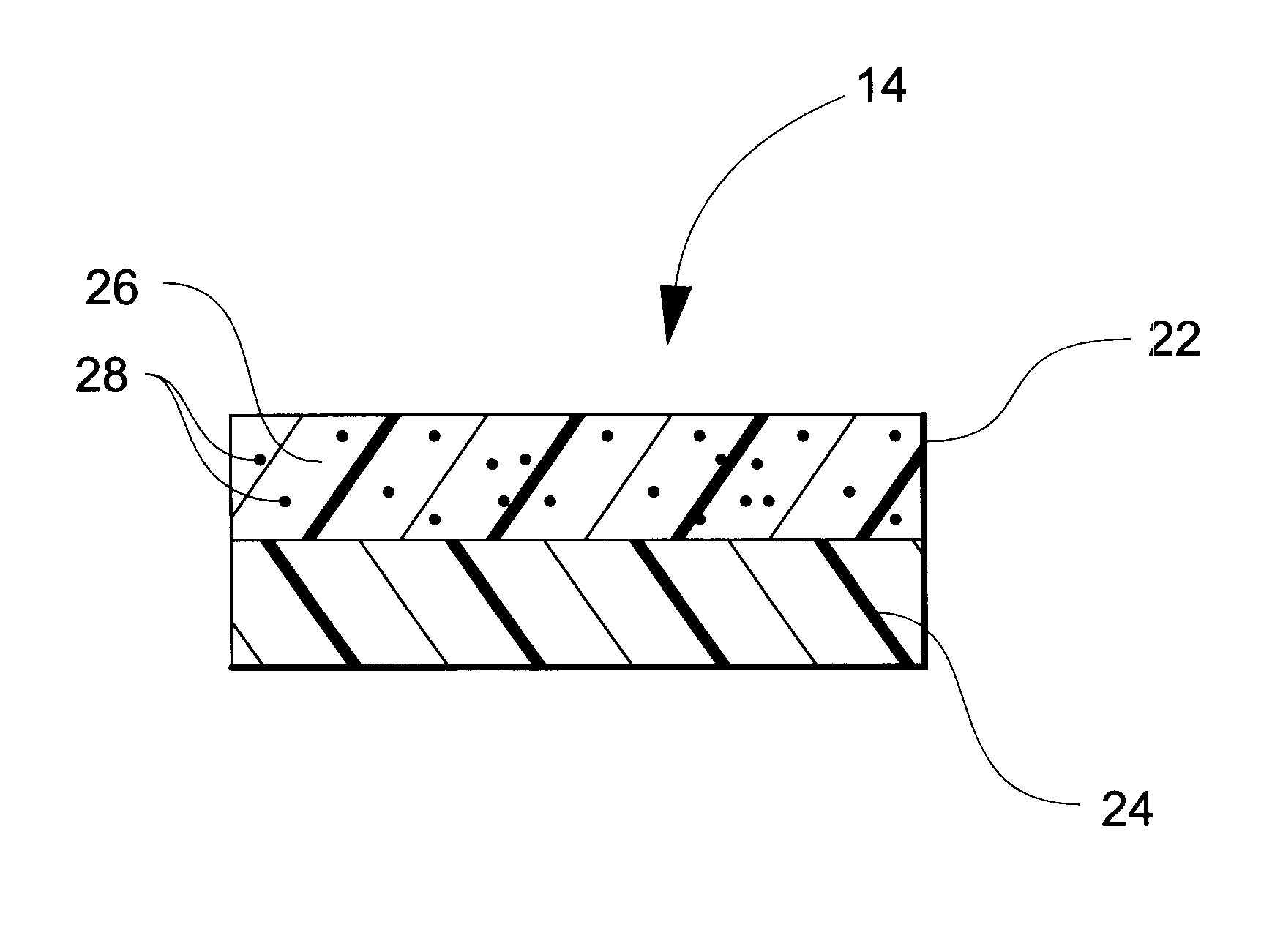
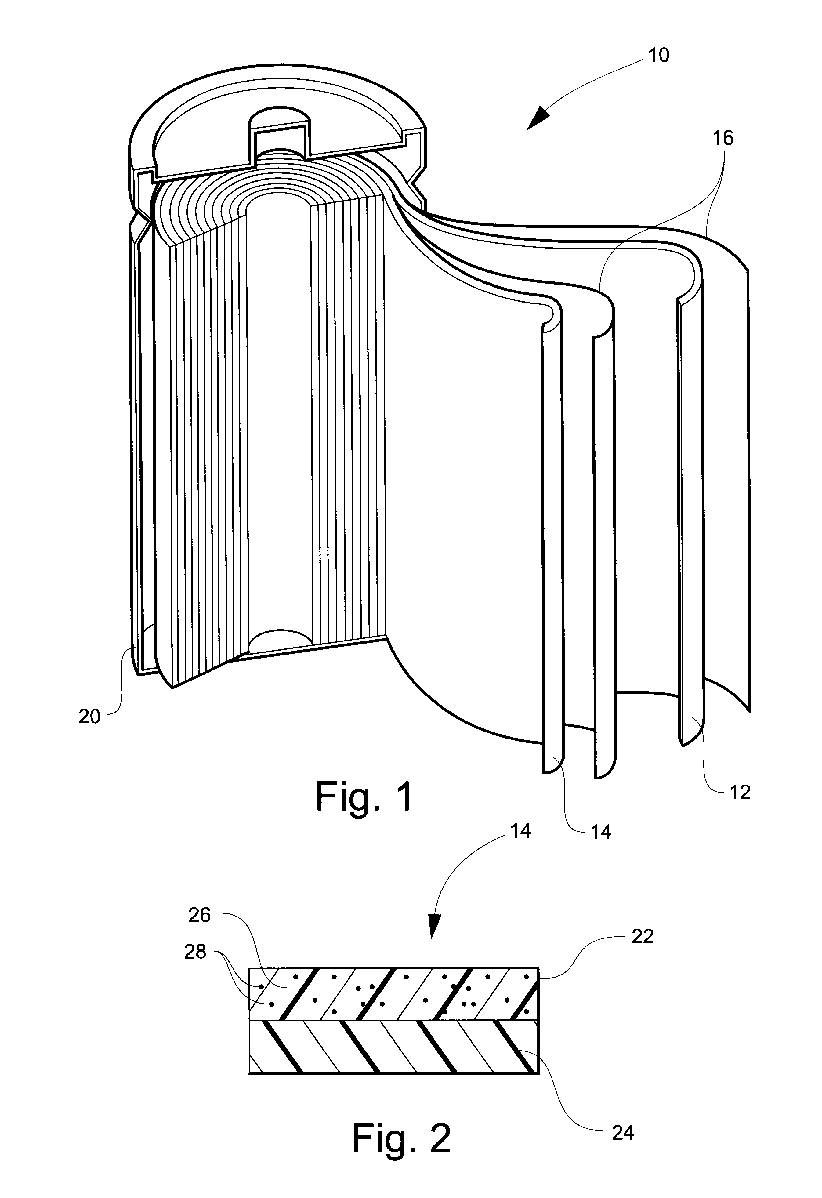
Sixty (60) parts of fine particle calcium carbonate, 40 parts of PVDF:HFP (Kynar 2801), are dissolved in 100 parts of acetone at 35.degree. C. for 3 hours under high shear mixing. The solution is cast into a 15 micron film. After vaporization of the actone at room temperature, the composite film was thermally laminated with 2 layers (8 microns) of Celgard 2801 membrane. The resulting composite shutdown separator has a structure of PE / composite / PE and a thickness of 30 microns.

Thirty (30) parts of silicon dioxide, 30 parts of calcium carbonate, 40 parts of PVDF:HFP (Kynar 2801) are dissolved in 100 parts of acetone at 35.degree. C. for 3 hours under high shear mixing. This solution was cast or coated onto a 23 micron layer of a polyethylene microporous layer made by Celgard Inc. After vaporization of the acetone at room temperature, the polyethylene / composite membrane had a thickness of 38 microns.

The present invention may be embodied in other specific forms without departing from th...


PUM

PropertyMeasurementUnit
pore sizeaaaaaaaaaa
porosityaaaaaaaaaa
particle sizeaaaaaaaaaa

Abstract

The instant invention is directed to a separator for a high energy rechargeable lithium battery and the corresponding battery. The separator includes a ceramic composite layer and a polymeric microporous layer. The ceramic layers includes a mixture of inorganic particles and a matrix material. The ceramic layer is adapted, at least, to block dendrite growth and to prevent electronic shorting. The polymeric layer is adapted, at least, to block ionic flow between the anode and the cathode in the event of thermal runaway.

Description

A separator for a high energy rechargeable lithium battery and a high energy rechargeable lithium battery are disclosed herein.A high energy rechargeable lithium battery has an anode with an energy capacity of at least 372 milliampere-hours / gram (mAh / g). Such anodes include, for example, lithium metal, lithium alloys (e.g. lithium aluminum), and mixtures of lithium metal or lithium alloys and materials such as carbon, nickel, and copper. Such anodes exclude anodes solely with lithium intercalation or lithium insertion compounds.The commercial success of lithium metal or lithium alloy batteries has eluded all but primary cells due to persistent safety problems.The difficulties associated with the use of the foregoing anodes stem mainly from lithium dendrite growth that occurs after repetitive charge-discharge cycling. (While dendrite growth is a potential problem with any lithium battery, the severity of the problem with the above-mentioned high energy anodes is much greater than wit...

Claims


Application Information

Patent Timeline
Patent Type & Authority Patents(United States)
IPC IPC(8): H01M2/16H01M10/052H01M10/36H01M50/414H01M50/417H01M50/42H01M50/426H01M50/443H01M50/451H01M50/457H01M50/491
CPCH01M2/164H01M2/1653H01M2/166H01M2/1686H01M10/052Y02E60/122Y02E60/10H01M50/446H01M50/457H01M50/451H01M50/414H01M50/491H01M50/443H01M50/417H01M50/42H01M50/426H01M50/434H01M50/489
Inventor ZHANG, ZHENGMING
Owner CELGARD LLC
Why Eureka
Try Eureka