Cluster tool architecture for sulfur trioxide processing

a technology of sulfur trioxide and tool architecture, which is applied in the direction of lighting and heating apparatus, furniture, charge manipulation, etc., can solve the problems of still vacuum-processing tools and art-architectures that cannot perform sulfur trioxide processing

Inactive Publication Date: 2002-09-17
BEST LABEL
View PDF3 Cites 38 Cited by
  • Summary
  • Abstract
  • Description
  • Claims
  • Application Information

AI Technical Summary

Benefits of technology

4. allows substrates to be replaced back into the cassette of or...

Problems solved by technology

However, it is still a vacuum-processing tool.
1. cluster tool processing is done only in a vacuum environment;
2. the atmospheric section of the cluster tool does not integrate atmospheric processing in a cluster format; and
3. tool architectures that have integrated vacuum and atmospheric processing have done so in a l...

Method used


Image

  • Cluster tool architecture for sulfur trioxide processing
  • Cluster tool architecture for sulfur trioxide processing
  • Cluster tool architecture for sulfur trioxide processing

Examples


Embodiment Construction

Reference is now made in detail to a specific embodiment of the present invention, which illustrates the best mode presently contemplated by the inventor for practicing the invention. Alternative embodiments are also briefly described as applicable.

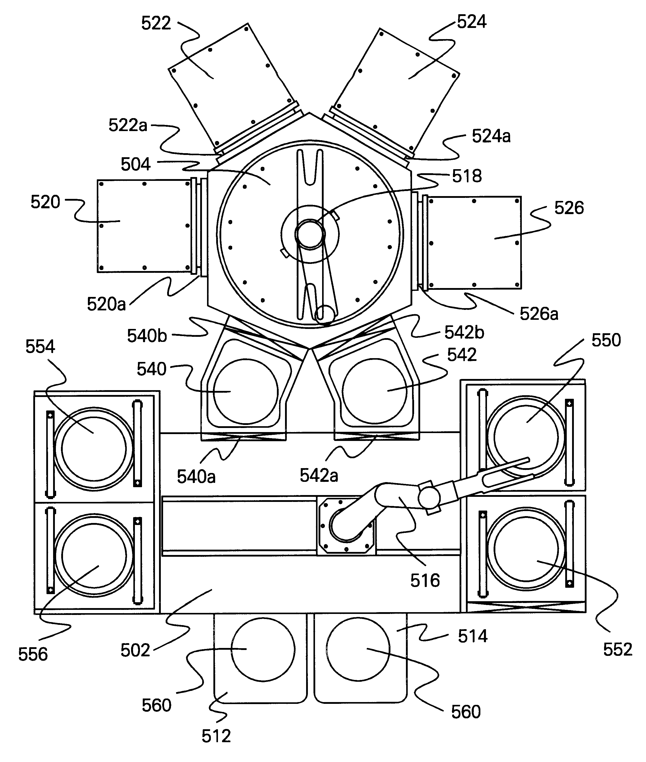
Integration of component processing by a combination of vacuum and atmospheric or high pressure processing is required, in a programmable order. The substrates, which in this case are silicon wafers, flat panel displays, thin film heads, hard disk drive substrates, hybrid circuit substrates, ink jet head substrates, flexible circuits, MEMS substrates or printed circuit boards, are processed in the following computer-controlled, programmed order automatically:

1. Unloading from a loading / unloading cassette or platform in a user-defined order by a robotic arm, in a controlled atmosphere or ambient or high pressure.

2. Aligning on the robotic arm or, if required, moving the substrate to a station, which finds a flat or notch and centers the ...


PUM

PropertyMeasurementUnit
Timeaaaaaaaaaa
Timeaaaaaaaaaa
Pressureaaaaaaaaaa

Abstract

A cluster tool architecture and method are provided for processing substrates by exposure to a process environment, including a reactive gas, such as sulfur trioxide, as well as prior and subsequent treatments thereto. The cluster tool architecture comprises: (a) an atmospheric processing area, maintained at atmospheric pressure or higher; (b) cassette means for introducing a plurality of the substrates into the atmospheric processing area; (c) at least one process station in the atmospheric processing area; (d) an enclosed vacuum processing area, maintained at a vacuum pressure; (e) a first buffer station between the atmospheric processing area and the enclosed vacuum processing area; (f) at least one process station in the enclosed vacuum processing area isolated from the enclosed vacuum processing area by an isolation valve for exposing the substrates to the process environment; (g) a second buffer station between the atmospheric processing area and the enclosed vacuum processing area; (h) an atmospheric transfer arm in the atmospheric processing area for transferring the substrates from the cassette means between one of the buffer stations and at least one process station in the atmospheric processing area and then to the cassette means; and (i) a vacuum transfer arm in the enclosed vacuum processing area for transferring the substrates from one of the buffer stations to one of the vacuum process stations in the enclosed vacuum processing area and from that vacuum process station in the enclosed vacuum processing area to the buffer station, wherein both buffer stations are equally accessible to both the atmospheric transfer arm and the vacuum transfer arm. The cluster tool architecture integrates atmospheric or high pressure processing with vacuum processing. Since integration allows random access, there is a freedom of programming process flow. The architecture allows re-entry of substrates, so that process steps can be repeated at any time, and it allows substrates to be replaced back into original cassette after process is complete.

Description

The present invention is directed to cluster tools for processing wafers and the like, and, more particularly, to a cluster tool architecture to be used, inter alia in sulfur trioxide processing of such wafers.Cluster tools have been available for many years. Such tools are used for automated processing of semiconductor wafers, for example. FIGS. 1-4 are schematic drawings of prior art cluster tools, and are shown here as an aid to differentiate the present invention from the prior art cluster tools.FIG. 1 depicts an example of prior art cluster tool architecture, 110, which is similar to a sputtering tool produced by Varian Associates. In this architecture, silicon wafers (not shown) are handled alternately from cassettes 112 and 114. First, the entire cassette assembly is pumped down to vacuum and the substrates are unloaded, one at a time, by means of a vacuum transfer arm 116 to an alignment station 117. The substrates are then loaded with a second arm 118 into one of several pr...

Claims


Application Information

Patent Timeline
IPC IPC(8): H01L21/00
CPCH01L21/67161H01L21/67167H01L21/67184
Inventor GARRIGA, RUDOLPH A.
Owner BEST LABEL
Why Eureka
Try Eureka