Flow sensor component

a flow sensor and component technology, applied in the direction of speed/acceleration/shock measurement, measurement devices, instruments, etc., can solve the problems of affecting the integration of microelectronic components in the diaphragm, and affecting the accuracy of measurement results

Inactive Publication Date: 2002-10-08
FRAUNHOFER GESELLSCHAFT ZUR FOERDERUNG DER ANGEWANDTEN FORSCHUNG EV
View PDF9 Cites 68 Cited by
  • Summary
  • Abstract
  • Description
  • Claims
  • Application Information

AI Technical Summary

Benefits of technology

The present invention combines the advantages of the use of silicon diaphragms and of diaphragms of dielectric material, e.g. silicon nitride and silicon oxide, with the possibility of flow direction measurement. The silicon diaphragm has the advantage that it can have a robust structural design and that it additionally permits the integration of temperature-sensitive electronic components in the diaphragm. The use of filled slots permits, in addition, an increase in the sensitivity by better thermal insulation of e.g. heating elements and thermal detection elements. When the flow sensor component according to the present invention is used, a dielectric passivation of the heating elements, of the temperature detection elements and of additional electronic components can be provided so as to avoid short circuits.

Problems solved by technology

A disadvantage of such an undercut structure is, however, that it is sensitive to e.g. dust and oil particles.
A disadvantage of such a system is the dependence of the thermal conductivity on outer influences, e.g. humidity, acting on the polyimide.
The structure described in this publication has a smooth surface and offers therefore no direct hold for particles or an impact pressure; it does, however, not permit an integration of microelectronic components in the diaphragm.
The sensitivity of these sensors is, however, low.

Method used


Image

  • Flow sensor component
  • Flow sensor component
  • Flow sensor component

Examples


Embodiment Construction

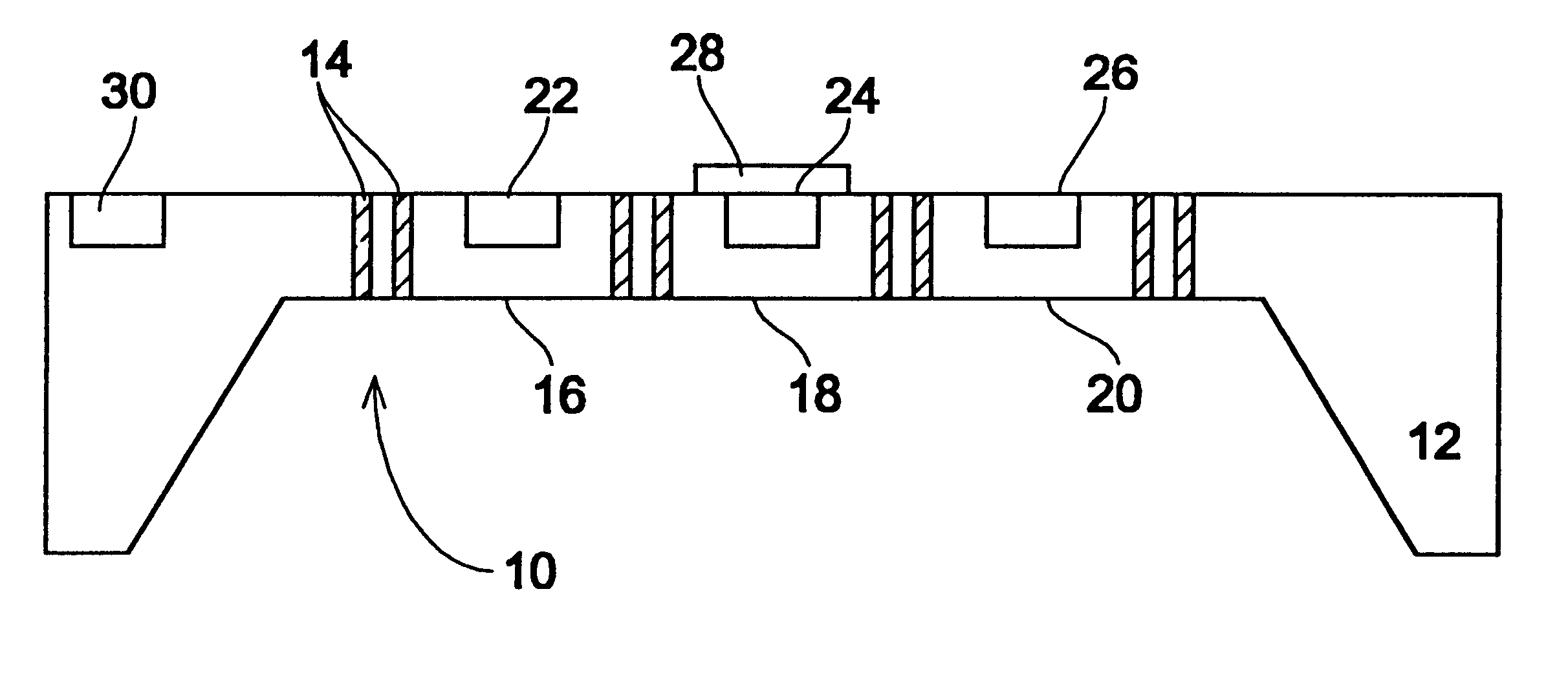
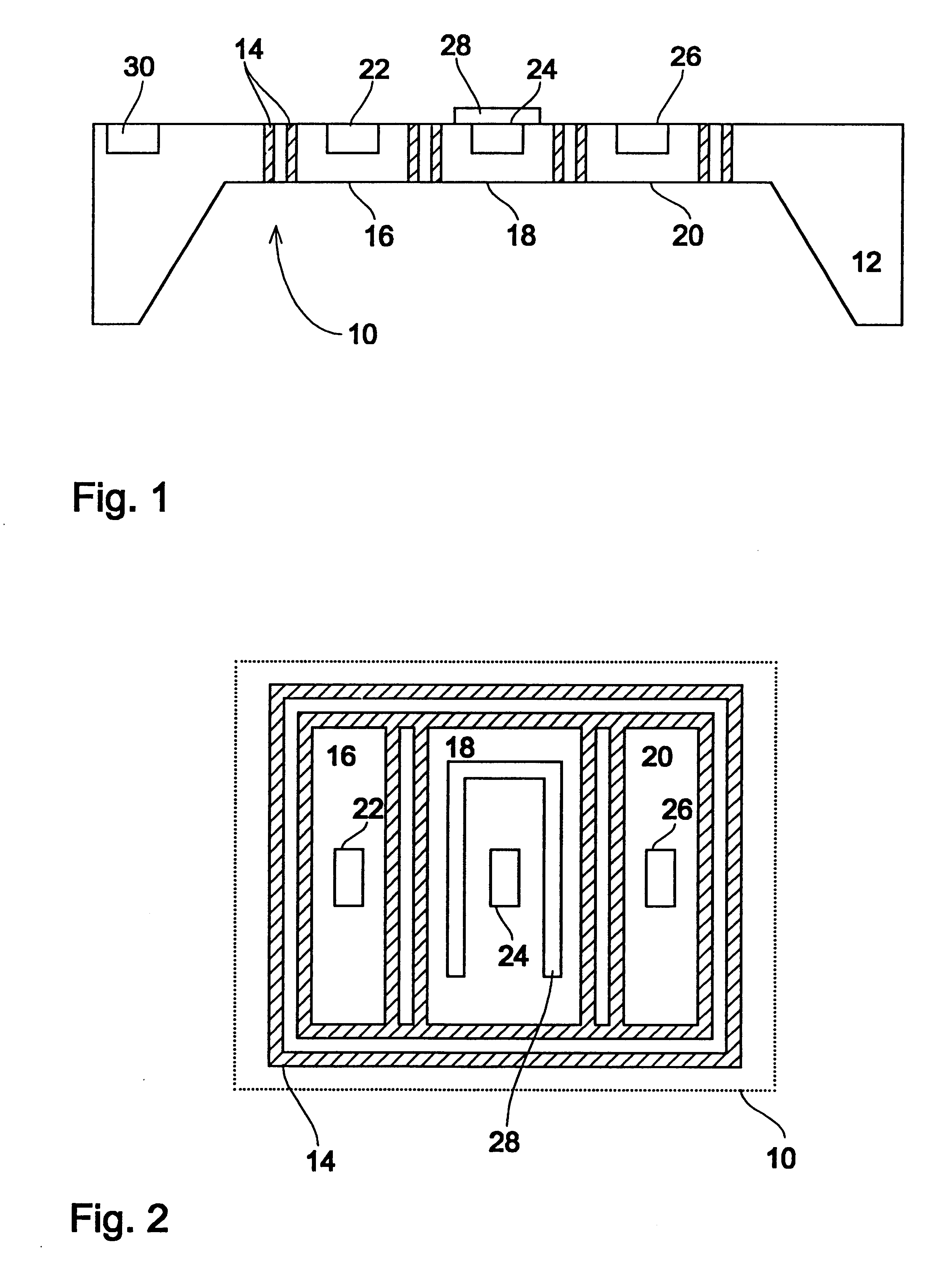
In FIGS. 1 and 2, a first embodiment of a flow sensor component according to the present invention is shown. A silicon diaphragm is formed in a silicon chip 12, e.g. by means of back etching. In the embodiment shown, filled slots 14 are arranged in the silicon diaphragm 10, the slots open at both ends 14 defining in the silicon diaphragm 10 three areas 16, 18 and 20 which are thermally insulated from one another. The filled slots extend from one main surface through the whole diaphragm 10 to a second main surface of the diaphragm. These filled slots are preferably filled with a dielectric material, which is silicon oxide in the case of the preferred embodiment. In the field of technology, such filled slots are referred to as filled layers also in the German language.

In the embodiment shown in FIGS. 1 and 2, a temperature detection element, i.e. a temperature sensor 22, 24, 26 is arranged in each of the thermally insulated areas. Furthermore, a heating element 28 is arranged in the c...


PUM


Abstract

A flow sensor component consists of a diaphragm of monocrystalline silicon, the diaphragm having arranged therein filled slots which are filled with a thermally insulating material and which penetrate the diaphragm from a first main surface to a second main surface thereof. The filled slots defining at least one heating area of the diaphragm provided with at least one heating element and at least one detection area of the diaphragm provided with at least one temperature detection element, the filled slots thermally insulating the heating area and the detection area from one another and surrounding the heating area and the detection area completely.

Description

1. Field of the InventionThe present invention relates to thermal semiconductor flow sensors with direction recognition for liquids and gases and, in particular, to a silicon flow sensor component for such flow sensors.Silicon technology-based sensors have promising properties for many measurement applications. They have, for example, small dimensions, they can be mass-produced at a reasonable price and they permit the monolithic integration of read-out electronics. Silicon flow sensors additionally offer the advantage of short response times and of a low power consumption. In the production process of the silicon sensors, integration of the electronics is, however, only possible if process steps, which are compatible with the production methods of microelectronics, are used for this integration of the electronics.2. Description of Prior ArtSilicon technology-based flow sensors are known, which operate on the basis of pressure-difference measurements. Such flow sensors are described...

Claims


Application Information

Patent Timeline
Patent Type & Authority Patents(United States)
IPC IPC(8): G01F1/684G01P13/02G01F1/704G01F1/708G01F1/7084
CPCG01F1/6845G01F1/7084G01P13/02
Inventor KERSJES, RALFMOKWA, WILFRIEDZIMMER, GUNTERVOGT, HOLGER
Owner FRAUNHOFER GESELLSCHAFT ZUR FOERDERUNG DER ANGEWANDTEN FORSCHUNG EV
Why Eureka
Try Eureka