Non-aqueous battery of a thin configuration

a thin configuration, non-aqueous technology, applied in the direction of secondary cells, jackets/case materials, cell components, etc., can solve the problems of difficult to reduce the weight of such a battery having a metallic casing, limited freedom of design of metallic casing shapes, and frequent short-circuit between terminals

Inactive Publication Date: 2002-10-08
ASAHI KASEI ELECTRONICS CO LTD
View PDF19 Cites 145 Cited by
  • Summary
  • Abstract
  • Description
  • Claims
  • Application Information

AI Technical Summary

Problems solved by technology

However, it is difficult to reduce the weight of such a battery having a metallic casing, and also there are limitations with respect to the freedom of designing the shapes of metallic casings.
Conventionally, the use of such a laminate for a battery casing has posed the following problems.
Further, after the production of the battery, a short-circuiting frequently occurs between the terminals and the metal foil layer exposed in the peripheral edge of the casing.
The occurrence of these short-circuitings are serious problems from the viewpoint of reliability and safety during the production and use of the battery.
However, batteries produced by this method do not solve the problem that a short-circuiting is likely to occur between the terminals and the metal foil layer exposed in the peripheral edge of the casing.
Moreover, this method is also disadvantageous in that, since the intermediate electrically insulating material layer employed in this me...

Method used


Image

  • Non-aqueous battery of a thin configuration
  • Non-aqueous battery of a thin configuration
  • Non-aqueous battery of a thin configuration

Examples


example 1

A powder of lithium cobalt oxide (LiCoO.sub.2 ; average particle diameter: 10 .mu.m) and carbon black were added to and dispersed in a 5% by weight solution of polyvinylidene fluoride (as a binder) in N-methylpyrrolidone (NMP), so that a mixture containing solid components in the following dry weight ratio was obtained: LiCoO.sub.2 (85%), carbon black (8%) and polyvinylidene fluoride (7%). The obtained mixture was applied onto an aluminum sheet (thickness: 15 .mu.m) (as a current collector) and dried, followed by heat-pressing, to thereby prepare a positive electrode layer having a thickness of 115 .mu.m and a density of 2.8 g / cm.sup.3. The aluminum sheet having the prepared positive electrode layer thereon was used as a positive electrode sheet. A powder of needle coke (NC) having an average particle diameter of 12 .mu.m was homogeneously mixed with a 5% by weight solution of polyvinylidene fluoride in NMP, thereby obtaining a slurry (NC / polymer dry weight ratio=92:8). The obtained...

example 2

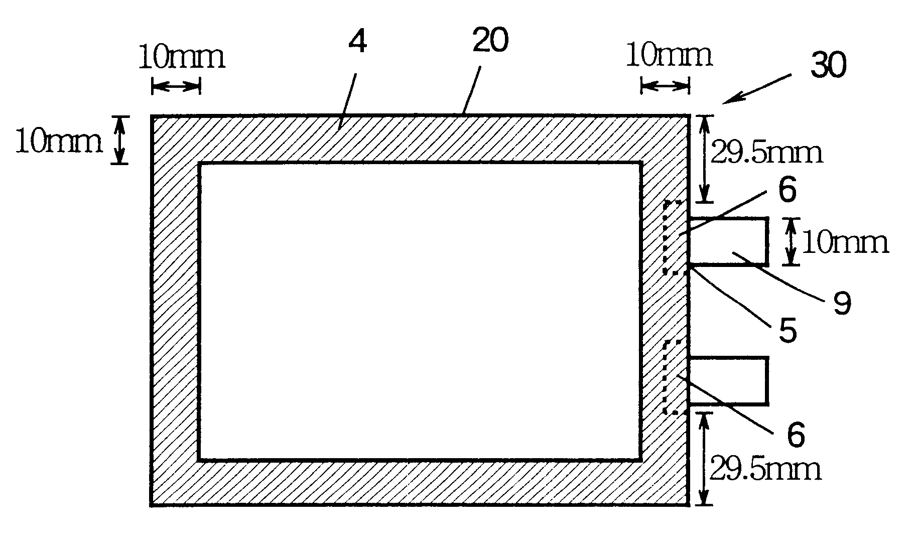
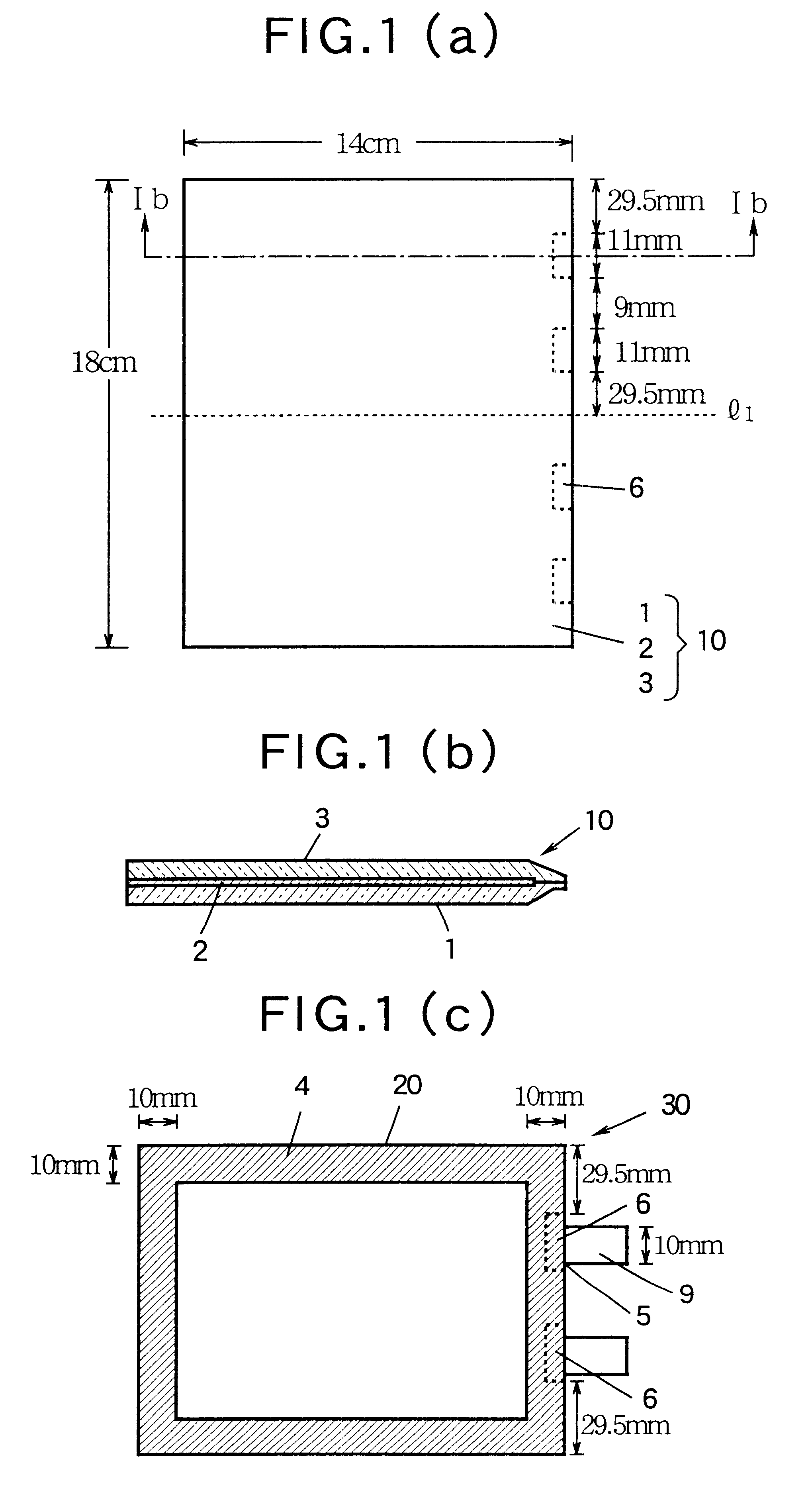
A laminate shown in FIGS. 2(a) and 2(b) for producing a pouchy casing for a battery was prepared in the following manner. Three different sheets respectively of a polyethylene terephthalate film (trade name: Melinex S, manufactured and sold by ICI Japan Ltd., Japan) having a length of 18 cm, a width of 14 cm and a thickness of 12 .mu.m; an aluminum foil having a length of 18 cm, a width of 13 cm and a thickness of 9 .mu.m; and an L-LDPE film (trade name: LS-700C, manufactured and sold by Idemitsu Petrochemical Co., Ltd., Japan) having a length of 18 cm, a width of 14 cm and a thickness of 50 .mu.m, were put one upon another in this order, wherein the sheets were trued up on their respective one 18 cm-sides. The sheets were adhered using a two-pack urethane adhesive to obtain a laminate. The aluminum foil in the laminate was cut-out along the entire length of one 18 cm-side of the foil by a depth (in a direction perpendicular to the peripheral edge of the foil) of 10 mm as measured f...

example 3

A laminate shown in FIGS. 3(a) and 3(b) for producing a pouchy casing for a battery was prepared in the following manner. Three different sheets respectively of a polyethylene terephthalate film (trade name: Melinex S, manufactured and sold by ICI Japan Ltd., Japan) having a length of 18.9 cm, a width of 14 cm and a thickness of 12 .mu.m; an aluminum foil having a length of 17.9 cm, a width of 13 cm and a thickness of 20 .mu.m; and a polyethylene-vinyl alcohol copolymer film (trade name: EF-HS, manufactured and sold by Kuraray Co., Ltd., Japan) having a length of 18.9 cm, a width of 14 cm and a thickness of 30 .mu.m, were put one upon another in this order, wherein the respective centers of the three sheets were in register with one another in which the sheets were adhered using a two-pack urethane adhesive to obtain a laminate. The thermoplastic resin layer and the electrically insulating material layer (polyethylene terephthalate film layer and polyethylene-vinyl alcohol copolymer...


PUM


Abstract

A non-aqueous battery is provided in a pouchy casing comprising opposing sheets of at least three-layer laminates, each laminate comprising (1) an inner thermoplastic resin layer, (2) a middle metal foil layer, and (3) an outer electrically insulating material layer, wherein the pouchy casing has an elongated, hermetic adhesion area along a periphery of the pouchy casing, and the middle metal foil layer has a peripheral elongated region in the elongated, hermetic adhesion area of the pouchy casing, and at least a pair of terminals electrically connected to the cathode and anode of the battery extends through and protrudes from the terminal-withdrawal sites in the elongated, hermetic adhesion area toward the outside of the pouchy casing, and the battery has at least one of the following features: (i) the peripheral elongated region of the middle metal foil layer has cut-out portions around the terminal-withdrawal sites and (ii) the surface of the peripheral edge of the pouchy casing is provided with electric insulation at least at portions around the terminal-withdrawal sites.

Description

FIELD OF THE INVENTIONThe present invention relates to a novel non-aqueous battery of a thin configuration. More specifically, the present invention is concerned with a non-aqueous battery of a thin configuration, comprising a hermetically sealed pouchy casing enveloping an electrochemical cell, and terminals electrically connected to a cathode and an anode of the electrochemical cell, wherein the pouchy casing comprises opposite sheets of at least-three-layer laminates, each comprising an inner thermoplastic resin layer, a middle metal foil layer and an outer electrically insulating material layer, and the pouchy casing has an elongated, hermetic adhesion area along a periphery of the pouchy casing, in which adhesion area the opposite inner thermoplastic resin layers are melt-adhered to each other, thereby forming a hermetic seal of the pouchy casing, wherein the middle metal foil layer (2) has a peripheral elongated region in said elongated, hermetic adhesion area of the poaching ...

Claims


Application Information

Patent Timeline
IPC IPC(8): H01M2/02H01M2/06H01M6/04H01M10/36H01M10/40H01M6/12H01M50/119H01M50/121H01M50/122H01M50/126H01M50/131H01M50/178
CPCH01M2/0275H01M2/06H01M6/12H01M10/0525Y02E60/10H01M50/126H01M50/121H01M50/178H01M50/119H01M50/122H01M50/131H01M50/105H01M50/543
Inventor SASAYAMA, MASA-AKIMINAKATA, TAKASHIYASUKATA, KOUICHI
Owner ASAHI KASEI ELECTRONICS CO LTD
Why Eureka
Try Eureka