
Universal equipment for the cooling fluid regeneration in heat exchange circuits

a technology of heat exchange circuit and cooling fluid, which is applied in the direction of domestic cooling apparatus, heating types, instruments, etc., can solve the problems of unsuitable frigorific circuits for different periods of the year or different specific needs, high water consumption, and high cost of recirculation, so as to achieve perfect calibration of the cooling plant and less water loss

Inactive Publication Date: 2002-10-22
HITACHI LTD
View PDF24 Cites 5 Cited by
  • Summary
  • Abstract
  • Description
  • Claims
  • Application Information

AI Technical Summary

Benefits of technology

at least one air draft generator device for forcing air through said cooling tower so as to cool the water and thereby minimize the water form evaporation;
Thus, the invention makes the cooling system more effective and with a higher yield, and reduces the temperature of the water to be cooled to a rather low value (reduced heat exchange thermal head).
In the preferred solution, said condensing means are placed both upstream and downstream of said tower, which makes possible a maximum cooling by operating in both conditions.
Another advantage is to perfectly calibrate the cooling plant with less water loss.
It is advantageous that the panel in contact with the cooling tower is extractable which makes possible a further cooling under certain conditions by operating only the frigorific circuit.

Problems solved by technology

Recirculation involves high costs and consumption of water which nowadays is so precious.
A water-air exchanger of the non-evaporating type (for example, dry-finned exchangers), the temperature at which the water may be regenerated cannot go below the temperature of the dry bulb of the air used and thus the range for temperature decrease is even more limited.
Also auxiliary cooling machines which use condensers operating in closed cycle frigorific circuits have the drawback of being unsuitable for different periods of the year or different specific needs.
It should also be considered that if the cooling apparatus does not always cool the machine with water in proportion, a vicious circle may actually endanger the machine and may even cause other damage.
Therefore, it would only be necessary to vary the water delivery for running the machine to be cooled perfectly, but this solution would be extremely expensive and ineffective in summertime.
In the case of a closed cooling circuit, if the cooling apparatus does not eliminate all the temperature increases, which the working machine yields, the closed circuit water temperature, tends to continuously increase in a vicious cycle which is difficult to eliminate without damaging the operating machine.
If it subtracts only 14.degree. C., at each water recirculation, the water will increase its temperature just a little less than one degree and even if progressively less, thereby reaches a point that endangers the work and damages the machine (operating) due to inadequate cooling of the operating machine circuit.
Vice versa, if the cooling apparatus subtracts too much temperature, the working machine would work in non-optimal temperature conditions.

Method used


Image

  • Universal equipment for the cooling fluid regeneration in heat exchange circuits
  • Universal equipment for the cooling fluid regeneration in heat exchange circuits
  • Universal equipment for the cooling fluid regeneration in heat exchange circuits

Examples


Embodiment Construction

These and other advantages will be apparent from the following description of a preferred solution, with the aid of the attached drawings whose execution details are not to be considered as the limits but are only given as examples.

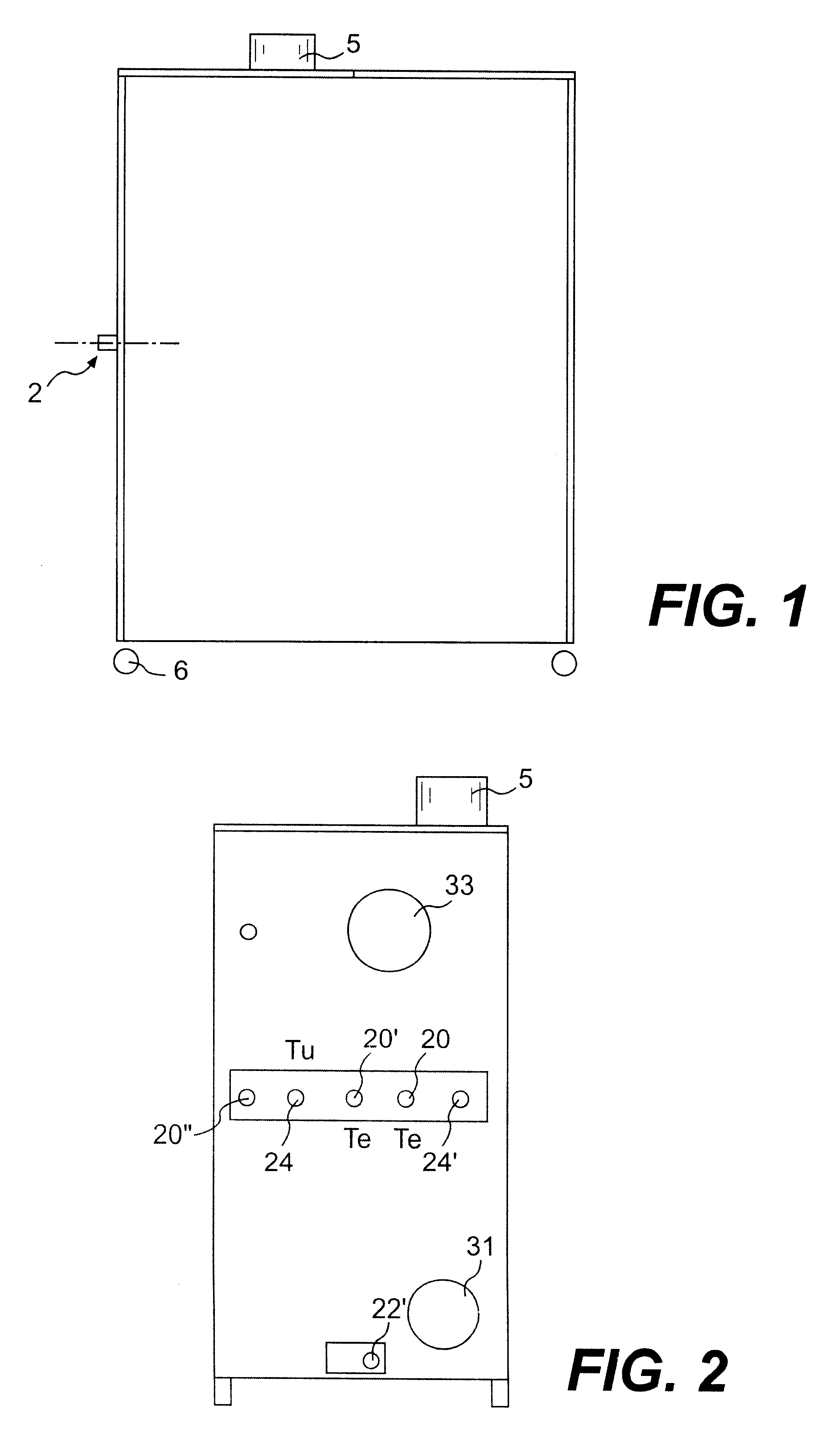
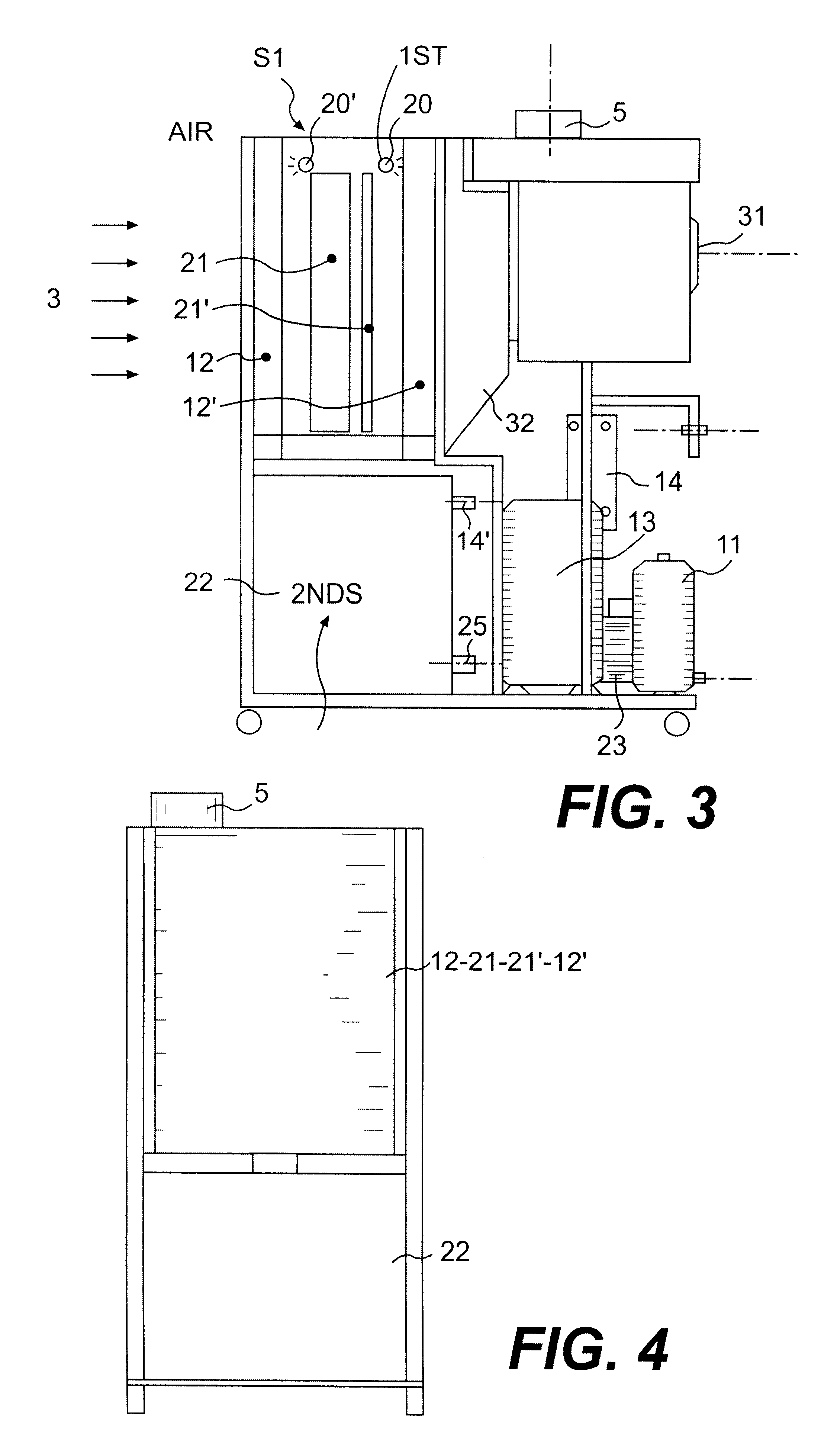
FIG. 1 is a side elevation schematic view of the equipment with covering panel which shows on the side that there are neither connections nor controls for making possible an adhesion to a wall or to another piece of equipment.

FIG. 2 is a rear elevation view of the equipment seen from the side where the connection pipes connect the water to the system, and of the circuit water which must be cooled in an operating machine.

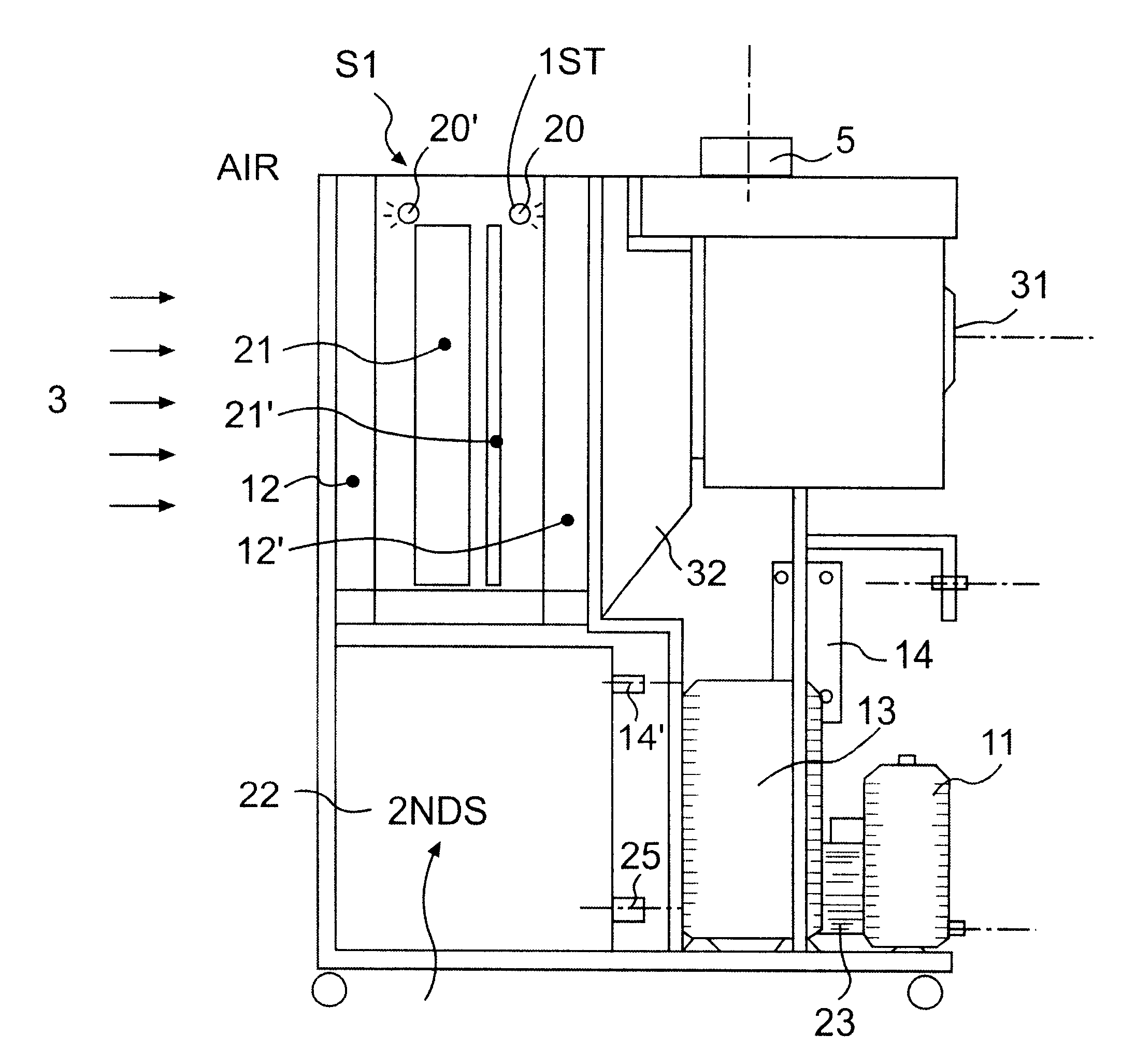
FIG. 3 is a side elevation view of the machine without the lateral covering panel showing the internal apparatus and devices.

FIG. 4 is a front view of the equipment in which a large mouth contacting the panelling for the heat exchange with the environmental air which is sucked towards the machine interior.

FIG. 5 shows the equipment interio...


PUM


Abstract

Cooling equipment, which may be connected to the water discharge from a working or operating machine with a water (20 / 20') cooling circuit (2) to make the water re-circulate once cooled (24), characterized in that the cooling equipment comprises: at least one cooling tower (21-21') with an extended surface for wetting and evaporation; at least one air flow generator device (3-31) for easing the evaporation; at least one closed cycle frigorific circuit (1) whose condenser (12) is placed downstream (12') of the cooling tower (21-21') with respect to the air flow (3-31) and whose evaporator (14) is placed downstream of the water cooling circuit (2) for exchanging heat with the cooled water (22) in the cooling tower (2-21') for then making the water re-circulate in the operating machine (24).

Description

The present invention provides the universal equipment for cooling fluid regeneration via heat exchange circuits.The invention applies water cooling heat exchange circuits to industrial machines such as ice cream production machines or plastic material moulding machines (moulds cooling), etc.It is known in the art that there are many types of machines using water cooling circuits which generally discharge the waste water without recirculation. Recirculation involves high costs and consumption of water which nowadays is so precious.The cooling water generally exits at a temperature about 35-40.degree. C.To avoid the high costs deriving from waste of the cooling water, equipment recirculating the water by cooling it were studied.This equipment is substantially made like a cooling tower which involves the recirculation of the water from the to-be-cooled machine, and is subject to a heat exchange by passing through a forced air-jet and by using an evaporating system, which eventually an...

Claims


Application Information

Patent Timeline
Patent Type & Authority Patents(United States)
IPC IPC(8): F28B1/06F28D5/00F28B1/00
CPCF28B1/06F28D5/00F25B2339/041Y10S165/90
Inventor MEDESSI, ENRICO
Owner HITACHI LTD
Learn More