Brightness enhancement for bistable cholesteric displays

a liquid crystal display and brightness enhancement technology, applied in the field of reflective cholesteric liquid crystal display, can solve the problems of low reflectance, low commercial value, and patent disclosure of brightness optimization methods, and achieve the effects of reducing cell spacing, high drive voltage, and reducing display cos

Inactive Publication Date: 2002-11-19
KENT DISPLAY SYST
View PDF30 Cites 30 Cited by
  • Summary
  • Abstract
  • Description
  • Claims
  • Application Information

AI Technical Summary

Benefits of technology

Another embodiment relates to the ability of the present invention to enable an inventive display to be fabricated with reduced cell spacing with a driver that can operate at a lower voltage or faster than in a comparative display having a cell spacing that is at least 10% greater than the reduced cell spacing, and yet have brightness that is at least as high as in the comparative display. In general, cholesteric displays require relatively high drive voltage. The display cost may be significantly reduced by reducing the drive voltage. As described in this disclosure, the present invention enables displays to be produced with enhanced brightness that in some cases may greatly exceed the brightness of typical displays. One conventional method of reducing the drive voltage is to reduce the cell spacing. However, this generally will also reduce the peak brightness. Due to the enhanced brightness feature of the present invention, inventive displays may obtain at least a conventional degree of brightness with reduced cell spacing effective to enable a lower drive voltage or faster drive to be used.
A display with reduced cell spacing according to this embodiment includes chiral nematic liquid crystal material having positive dielectric anisotropy. Cell wall structure is spaced apart at a reduced cell wall spacing contains the liquid crystal material. At least one alignment surface is effective to substantially homogeneously align the liquid crystal director adjacent thereto. At least one of the cell wall structure and each alignment surface cooperates with the liquid crystal material so as to form focal conic and planar textures that are stable in the absence of a field. Each alignment surface is effective to increase brightness at a wavelength of peak reflection of the planar texture so as to be at least as high as a brightness of the identical comparative liquid crystal display device but with inhomogeneous alignment surfaces and a comparative cell wall spacing that is at least 10% greater. A device applies a drive voltage effective to transform the liquid crystal material to at least one of the focal conic and planar textures.
The reduced cell wall spacing may be effective to enable the drive voltage to be substantially less than a drive voltage of the comparative liquid crystal display device while maintaining the same peak brightness. Reduced cell wall spacing may also be effective to increase the drive speed while maintaining the same peak brightness and drive voltage of the comparative display device.

Problems solved by technology

However, the U.S. Pat. No. 5,453,863 patent does not address the relationship between display performance and variations in the degree of rubbing and choice of alignment layer materials.
More importantly, that patent does not disclose how to optimize brightness by increasing the reflectivity of the planar texture or how to optimize contrast by lowering reflectance of the focal conic state.
A display with a focal conic state that has high reflectance will have low contrast and is of little commercial value.
A drawback with current cholesteric liquid crystal displays, however, is that their brightness and contrast are not optimized.
Defects also tend to destroy the polarization state of the reflections from the planar texture.
Likewise, contrast has been limited by the light scattering nature of the focal-conic texture.
However, such an alignment condition alone does not stabilize the focal-conic texture and provide it with desirable low reflectance.

Method used


Image

  • Brightness enhancement for bistable cholesteric displays
  • Brightness enhancement for bistable cholesteric displays
  • Brightness enhancement for bistable cholesteric displays

Examples


example 1

Cells Rubbed On One Side

A display was prepared having a homogeneous alignment surface in the form of a rubbed polyimide on only one substrate. The other substrate included an unrubbed layer of polyimide (inhomogeneous alignment surface) and served to stabilize the focal conic texture. The display comprised four separate test cells, each of the test cells including opposing glass substrates separated by 5 .mu.m glass cell spacers (this cell spacing being used in all cells discussed in this disclosure). The arrays were assembled and vacuum filled with the following Merck cholesteric liquid crystal mixture: 75.60% BLO61, 23.90% E44 and 00.50% C6. Disposed on both glass substrates from the manufacturer (Applied Films Corp., T1X0100 in all examples herein) was a hardcoat and ITO electrodes. Applied to this was a Nissan 720 hard coat material for preventing shorting in the well known manner (800 Angstroms ".ANG." on both sides). On top of this was Nissan 7511 polyimide alignment layer (25...

example 2

Cells Rubbed on Both Sides

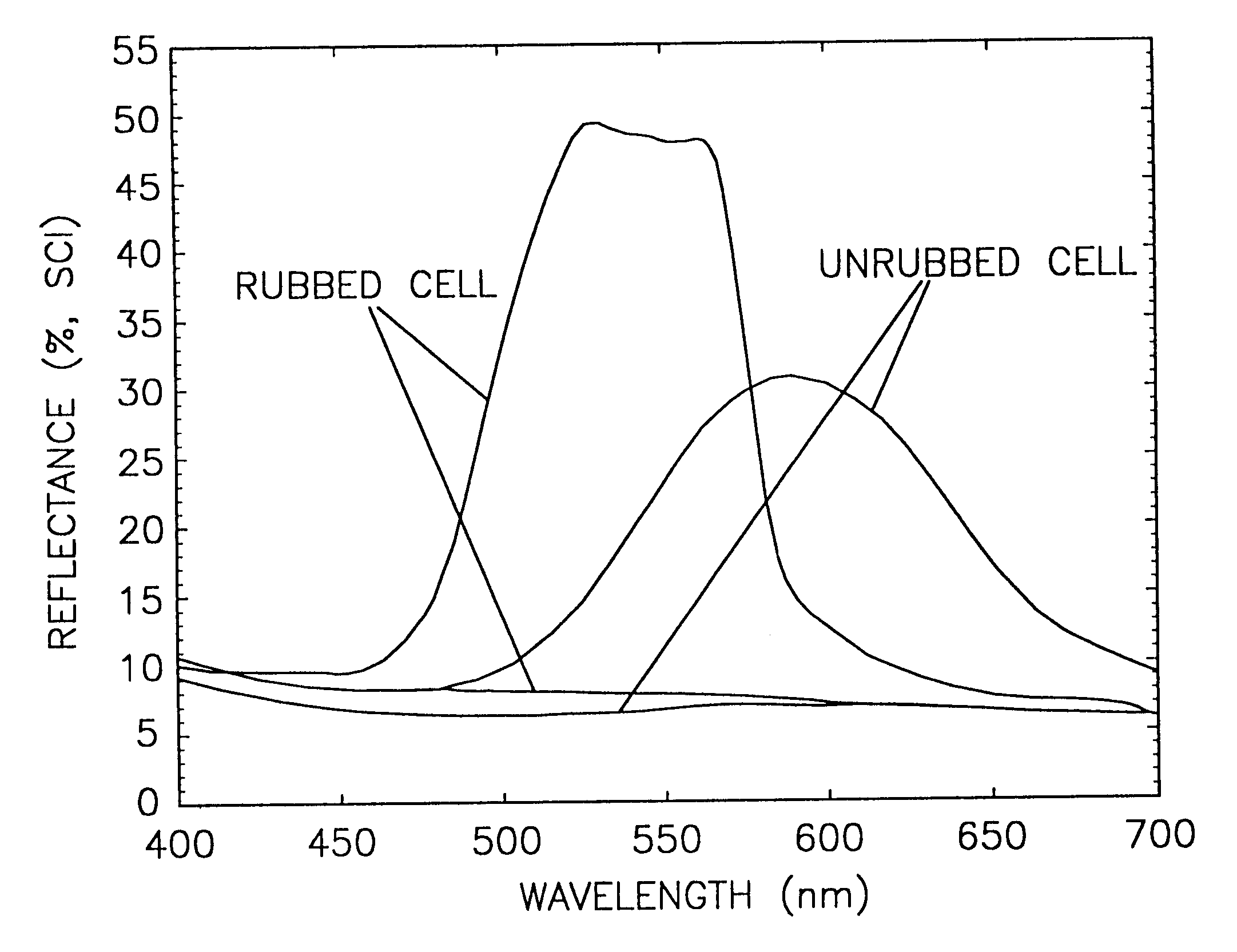
Another embodiment of the present invention employs a homogeneous alignment surfaces in the form of rubbed polyimide layers each disposed adjacent one of the substrates. The display comprised opposing glass substrates separated by a 5 .mu.m cell spacing. The display was assembled and vacuum filled with the following Merck cholesteric liquid crystal mixture: 77.60% BL061, 12.10% E44, 10.0% pcyanopentylbenzene as described in U.S. patent application Ser. No. 08 / 862,561, entitled "Low Viscosity Liquid Crystal Material", which is incorporated herein by reference, and 00.30% C6, the reflectance curves of which are shown in FIGS. 9 and 10. The unrubbed cell shown in FIG. 9 included 75.6% BL061, 23.9% E44 and 0.50% C6. Disposed on both substrates was Nissan 720 hard coat material (800A on both sides), and on top of this was Nissan 7511 polyimide alignment layer (250 .ANG.). The same substrates with hardcoat and ITO coatings described in Example 1 were used here. A...

example 3

Alignment Layer Materials

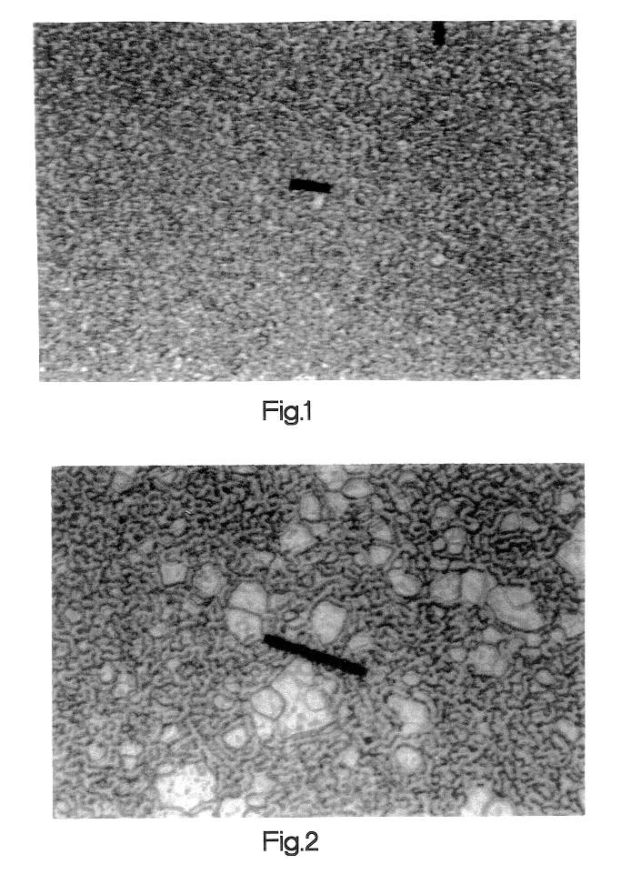
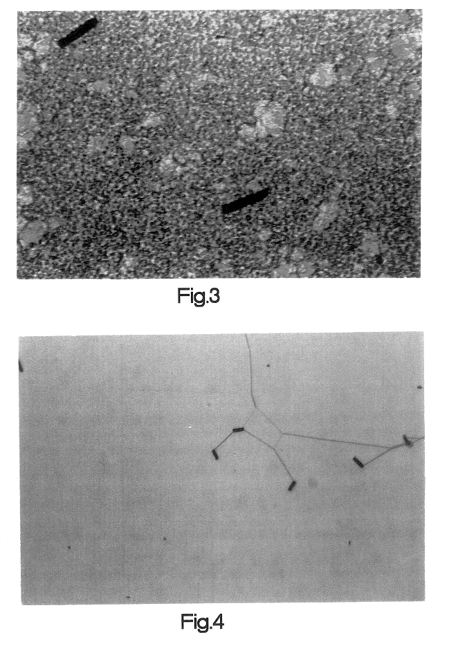
Three types of cells were prepared each with a different alignment layer material, Cells 1, Cells 2 and Cells 3. All of Cells 1 were prepared with Nissan 7511 polyimide alignment material, all of Cells 2 were prepared with Nissan 5211 polyimide alignment material and all of Cells 3 were prepared with DuPont 2555 polyimide alignment material. Three cells were prepared using each type of alignment layer material for a total of nine cells. In FIGS. 12-17, for each type of alignment layer material there was prepared one cell having both sides unrubbed (e.g., "C1.sub.UR-P "), one cell having one side rubbed and one side unrubbed (e.g., "C1.sub.OSRU-P ") and one cell having both sides rubbed (e.g., "C1.sub.BSR-P "). Portions of these designations are underlined in the text for emphasis and are not underlined in the drawings. In the figures, cells rubbed on only one side were provided with further designations regarding whether the rubbed side was up ("U") or down ...


PUM

PropertyMeasurementUnit
reflectanceaaaaaaaaaa
pretilt angleaaaaaaaaaa

Abstract

The present invention is directed to a cholesteric liquid crystal display that includes a homogeneous alignment surface effective to provide increased brightness, low focal conic reflectance and/or reflected light that is to a significant degree circularly polarized. The homogeneous alignment surface substantially homogeneously aligns the liquid crystal director adjacent thereto. The homogeneous alignment surface may be disposed on one or both sides of a cell of the display. In the case of a cell in which the homogeneous alignment surface is disposed on only one side, the substrate with the inhomogeneous alignment surface may be upstream or downstream of the substrate with the homogeneous alignment surface relative to a direction of incident light. Also included especially in the case of a cell that has the homogeneous alignment surface on both sides is the use of a polarizer to provide very good brightness and low focal conic reflectance. Such a cell may employ an alignment layer material with a high pretilt angle. A stacked display may be produced including at least one cell with at least one homogeneous alignment surface. In particular, a stacked cell display may include a lower cell with two homogeneous alignment surfaces and an upper cell in which the top side has an inhomogeneous alignment surface and the bottom side has a homogeneous alignment surface. The present invention achieves any one or combinations of the above features through the use of the homogeneous alignment surface produced with a predetermined alignment layer material and predetermined alignment conditions. The invention also includes a method of making the inventive display and the stacked inventive display.

Description

FIELD OF THE INVENTIONThe present invention is directed to reflective cholesteric liquid crystal displays and, in particular, to the use and treatment of alignment layer materials to improve performance of such displays.BACKGROUND OF THE INVENTIONLiquid crystal displays have brought to the world a low-power, flat-screen technology that has enabled many new portable devices. As the demand for more portable devices grows, so does the demand for displays with improved performance. Reflective displays are important not only because they reduce power consumption, but also because they can be clearly seen in sunlight. Displays with bistable memory are attractive for reducing power consumption and increasing battery life compared to displays in which the image needs to be continuously refreshed.Bistable liquid crystal displays were developed using cholesteric liquid crystalline materials. With a low concentration polymer network, both the focal-conic and planar textures of a cholesteric li...

Claims


Application Information

Patent Timeline
Patent Type & Authority Patents(United States)
IPC IPC(8): G02F1/1335G02F1/1337G02F1/137G02F1/13
CPCG02F1/133528G02F1/13718G02F1/133536G02F1/133555G02F1/133723G02F2001/133541G02F2001/133738G02F2001/133757G02F1/133541G02F1/133738G02F1/133757
Inventor KHAN, ASAD A.HUANG, XIAO-YANGDOANE, J. WILLIAMMICELI, GENE A.DAVIS, DONALD J.
Owner KENT DISPLAY SYST
Why Eureka
Try Eureka