Manifold for use in cleaning combustion turbines

a combustion turbine and manifold technology, applied in the direction of machines/engines, liquid fuel engines, machine/engines, etc., can solve the problems of reducing the efficiency and power output of the compressor, the surface of the compressor blades and vanes becomes coated with contaminants, and the fuel consumption increases, so as to improve the efficiency and economy of the combustion turbine, improve the discharge pressure of the compressor and the turbine, and reduce the effect of fuel consumption

Inactive Publication Date: 2002-12-10
GENERAL ELECTRIC CAPITAL AS AGENT
View PDF22 Cites 82 Cited by
  • Summary
  • Abstract
  • Description
  • Claims
  • Application Information

AI Technical Summary

Benefits of technology

In a preferred embodiment of the present method, a second, foamed cleaning solution suitable for removing contaminants produced during the combustion process and deposited on the internal surfaces on the combustion and turbine sections is prepared. These contaminants often include heavy metals and their oxides, together with shellacs, varnishes and other hard combustion residues. Accordingly, preferred cleaning solutions include aqueous solutions of an acid and a foaming agent. Suitable acids include both organic and inorganic acids. Particularly preferred are dilute solutions of the mineral acids. These solutions often include an appropriate corrosion inhibitor. Because the acidic cleaning solutions are typically not needed to remove contaminants from the compressor section and because these stronger solutions may attack and damage the vanes and blades therein, these stronger cleaning solutions should be prevented from entering the compressor section. In a preferred embodiment, this goal is accomplished by initially filling the compressor section with a first, foamed cleaning solution appropriate for cleaning the compressor section and continuing to pump that first solution through the compressor section while pumping the second, stronger cleaning solution through the combustion and turbine sections.
The prepared foams provide acceptable cleaning results throughout a wide temperature range. While they typically function throughout the full temperature range where the underlying solution is liquid, i.e., from about 32.degree. F. to about 212.degree. F. for aqueous solutions, they are most often used at temperatures ranging from ambient, i.e., about 40-80.degree. F., to about 200.degree. F. Because the effectiveness of most cleaning solutions is improved at higher temperatures, most foam solutions are used at a temperature of about 150-180.degree. F. for maximum efficiency.
While it not necessary to turn the turbine during the cleaning operation, it is believed that penetration of the foam is improved by slow cranking of the turbine. Accordingly, it is preferred that the turbine be turned at a speed not exceeding about 10 RPM, preferably about 5 RPM during the pumping operations.
When installed, the manifold of the present invention provides a convenient means for pumping a foamed cleaning solution through the compressor section of a combustion turbine to perform the cleaning methods of the present invention. By employing the cleaning methods of the present invention, contaminants in both the compressor section and in the combustion and turbine sections of a combustion turbine are conveniently and effectively removed in order to improve the compressor and turbine discharge pressures and the turbine power output, thus improving the efficiency and economy of the combustion turbine.

Problems solved by technology

Unfortunately, the surfaces of the compressor blades and vanes become coated with contaminants of various types during use.
As the airflow through the compressor section diminishes, the compressor discharge pressure drops, resulting in a reduction in compressor efficiency and power output from the turbine.
The resulting inefficiency causes an increase in fuel consumption and a loss in power generation output.
All of these surface deposits alter the ideal air foil surface shape, disturbing the desired air flow over the blades and vanes.
This results in a reduction in the pressure rise across each successive turbine stage and a drop in overall turbine efficiency.
Because many liquid solvents also attack the engine components, the injection of liquid solvents into the engine has often proven to be unacceptable.
However, abrasive materials have proven to be unsatisfactory.
Such materials are often overly abrasive, not only dislodging contaminants but also destroying the surface smoothness of the blades and vanes.
Furthermore, some of these abrasive materials generally remain within the engine.
If non-combustible, these materials may clog cooling holes of the turbine components and restrict needed cooling airflow.
If combustible, these materials may produce residues which clog the cooling holes.
It has been observed, however, that water washes such as those described above only clean the first few rows of compressor blades and vanes.
Further, water washes provide no benefit with respect to fouling occurring in the combustion and turbine sections of the turbine.
While addressing the evaporation problem, however, Woodson's solution did not solve the problem resulting from centrifugal forces developed as the turbine spins during operation.
While more effective than the previously described on-line cleaning procedures, the unit must be taken out of service, thus, increases costs through loss of output during the cleaning operation.
Unfortunately, non-combustible abrasive particles often clogged small cooling holes in the turbine blades, while combustible particles produced further residues on the blades.
While these combustible coke abrasives avoided many of the problems found with prior art abrasive particles, they still did not provide a complete and full cleaning of the internal surfaces.

Method used


Image

  • Manifold for use in cleaning combustion turbines
  • Manifold for use in cleaning combustion turbines
  • Manifold for use in cleaning combustion turbines

Examples


Embodiment Construction

The present invention provides a manifold useful with improved methods for removing contaminants deposited on the blades and vanes of the compressor, combustion and turbine sections of a combustion turbine. The present invention provides improved, off-line methods for cleaning such turbines by using a manifold to pump a foamed cleaning solution through the air intake of the combustion turbine.

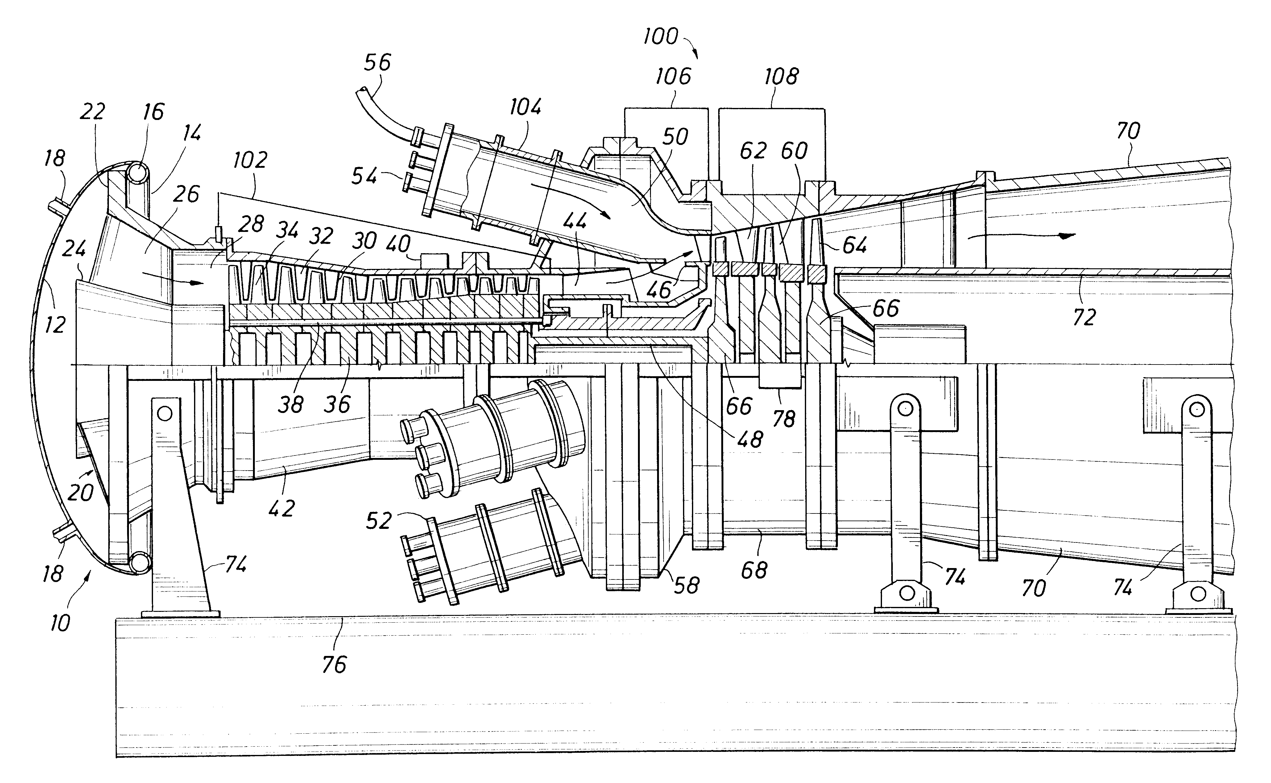
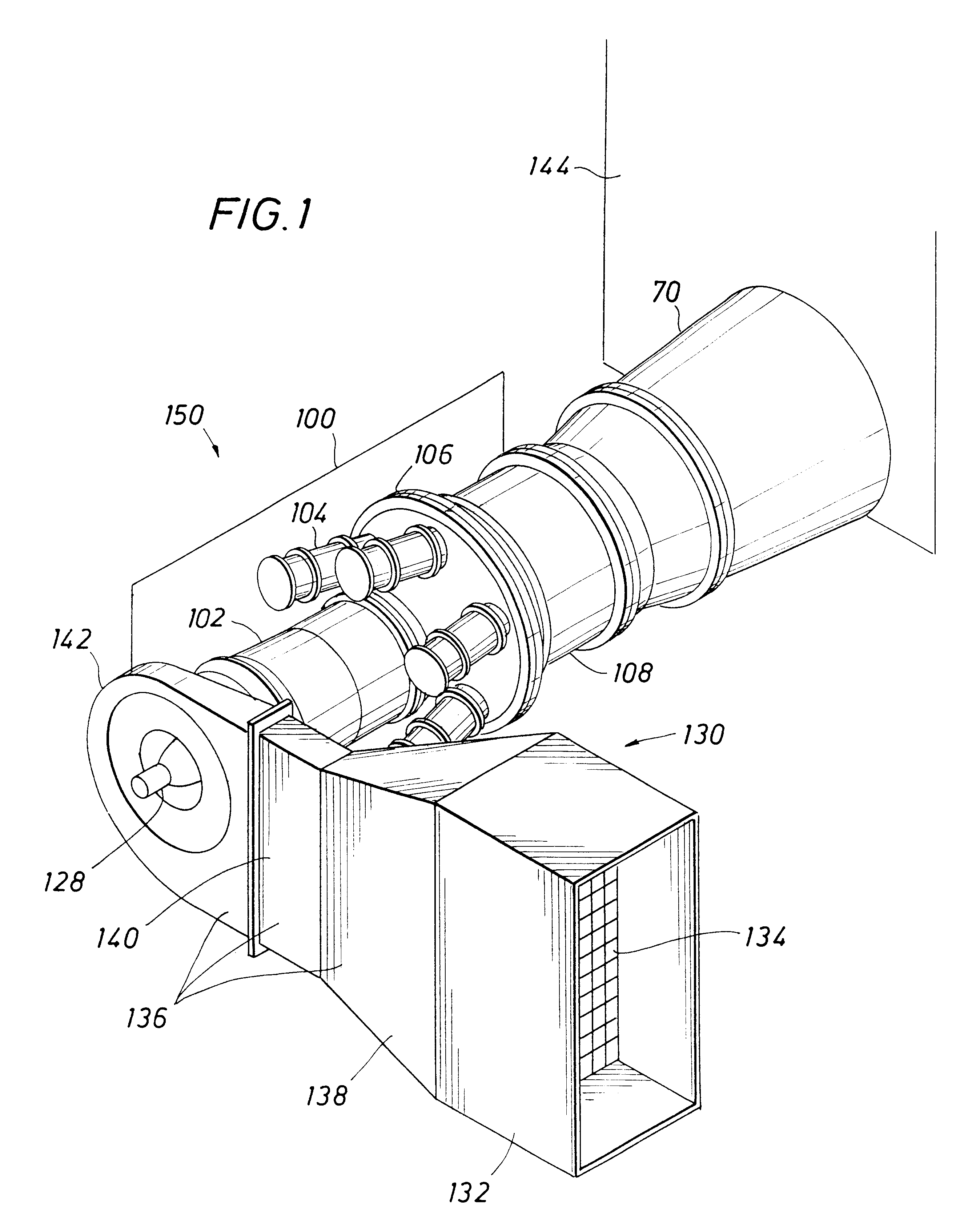
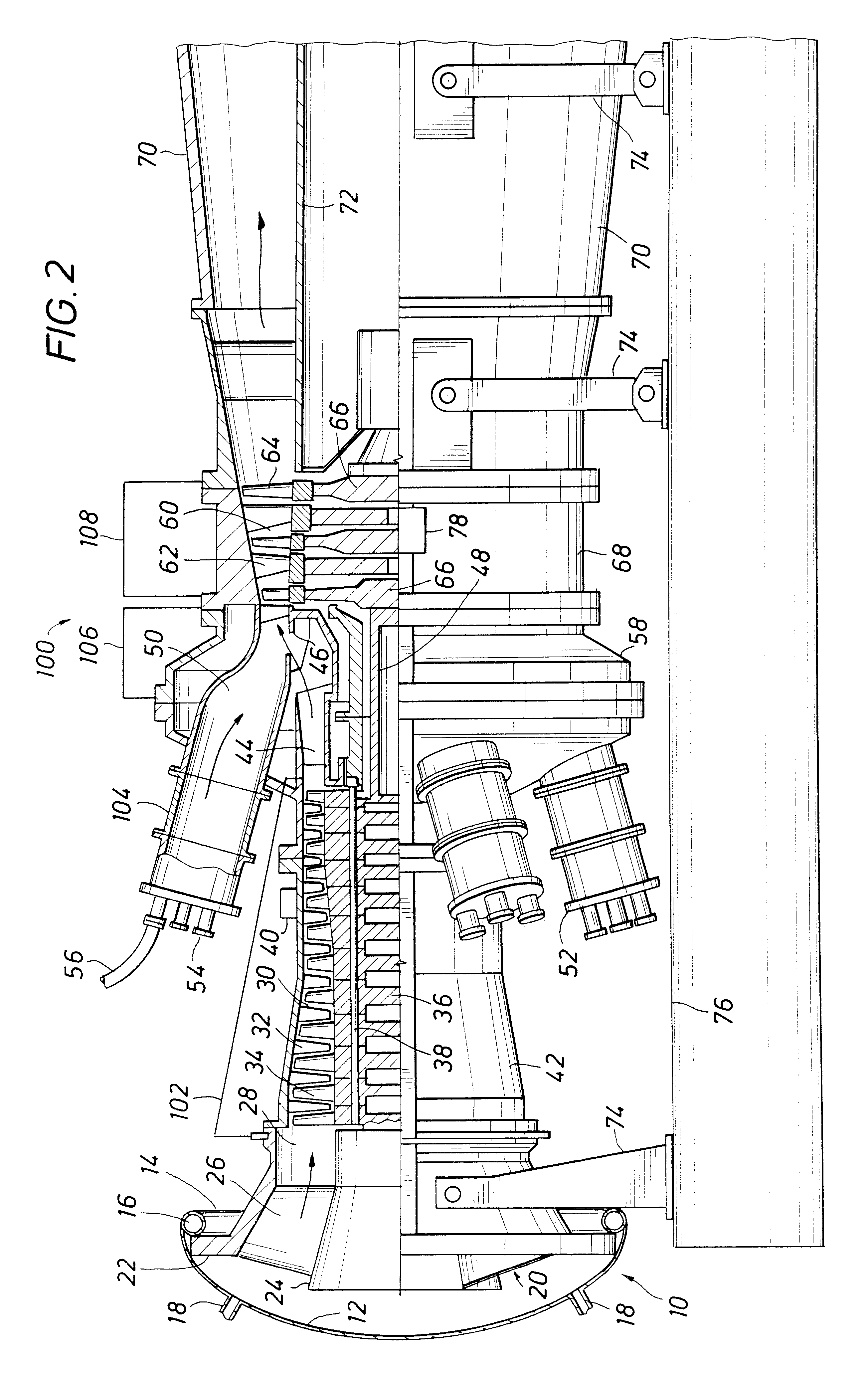
The present invention is readily understood by reference to the operation of an otherwise conventional, combustion turbine power generation facility such as illustrated in FIG. 1. FIG. 1 provides an overview of a combustion turbine power generation facility 150. Combustion turbine engine 100 is employed to generate electric power from the combustion of fuel with air. For simplicity, the associated electric generator is not illustrated in FIG. 1.

Depending on the installation, the electric generator can be driven from either the intake end of turbine engine 100 via shaft 128 or from the exhaust e...


PUM


Abstract

The present invention is directed to a manifold for temporarily blocking the air intake of the compressor section of a combustion turbine to facilitate cleaning. A manifold suitable for providing a temporary seal about the air intake of the compressor section and through which a foamed cleaning solution can be pumped is disclosed. The manifold is conveniently provided as a flexible manifold body having an inflatable tubular member along the periphery thereof for sealing with the air intake and a plurality of hose connections through which a foamed cleaning solution can be delivered to the compressor section of the combustion turbine. Particulate films and contaminants adhering to the internal components of the compressor section of a turbine are readily removed by pumping a foamed cleaning solution such as a foamed, aqueous surfactant solution through the manifold and into the compressor section. Contaminants resulting from fuel combustion and deposited in the combustion and turbine sections are removed by pumping a second, foamed cleaning solution through those sections. The second solution typically comprises a foamed, aqueous acid solution optionally including a corrosion inhibitor. The compressor section must be isolated from such acid solutions, e.g. by pumping the foamed surfactant solution through the manifold and compressor section prior to and simultaneously with pumping the foamed acid solution through the combustion section.

Description

BACKGROUND OF THE INVENTIONI. Field of the InventionThe present invention generally relates to an apparatus useful with methods for cleaning combustion turbines. The present invention is useful with methods for cleaning contaminants adhering to the internal surfaces of the compressor, combustion and turbine sections of a combustion turbine by pumping one or more foamed cleaning solutions therethrough. More specifically, the present invention is directed to a manifold for temporarily blocking the air intake opening of the compressor section of a combustion turbine to facilitate such cleaning.II. Description of the BackgroundCombustion turbines are used in a multitude of applications, including aviation, shipping, chemical processing and power generation. In combustion turbine power generation facilities, efficiency can be improved by supplementing the electrical power generated directly from the combustion turbine with recovery units designed to capture heat from the exhaust gas gene...

Claims


Application Information

Patent Timeline
Patent Type & Authority Patents(United States)
IPC IPC(8): F01D25/00F02C7/00
CPCF01D25/002F02C7/00F04D29/705
Inventor FOSTER, CHARLES D.
Owner GENERAL ELECTRIC CAPITAL AS AGENT
Why Eureka
Try Eureka