It is a primary object of the present invention to provide a method for continuous casting of metal wherein the flow in the mold is controlled during casting by an on-
line regulation of the magnetic flux density of a magnetic field applied to act on the metal to
brake and split the incoming primary flow of hot metal and form a controlled secondary flow pattern in the mold. The on-
line regulation shall be provided throughout essentially the whole casting and be based on the actual casting conditions or operating parameters prevailing in the mold or effecting the conditions in the mold at that moment to provide a cast product with a minimum of defects produced at the same or improved productivity.
Other advantages of the present invention will became apparent from the description of the invention and the preferred embodiments of the invention, including its capabilities to provide an improved and controlled flow pattern throughout the casting also when one or more parameters change and the thereby increased capability to, over a wide range of operating parameters, mold dimensions, metal compositions, etc., control the solidification conditions in the cast product, conditions for removal of non-
metallic impurities from the cast product and the
entrapment of mold
powder or gas in the cast products, so that even when one or more of these parameters changes for whatever reason during casting, the casting conditions can remain essentially stable or be adjusted to be within preferred limits.
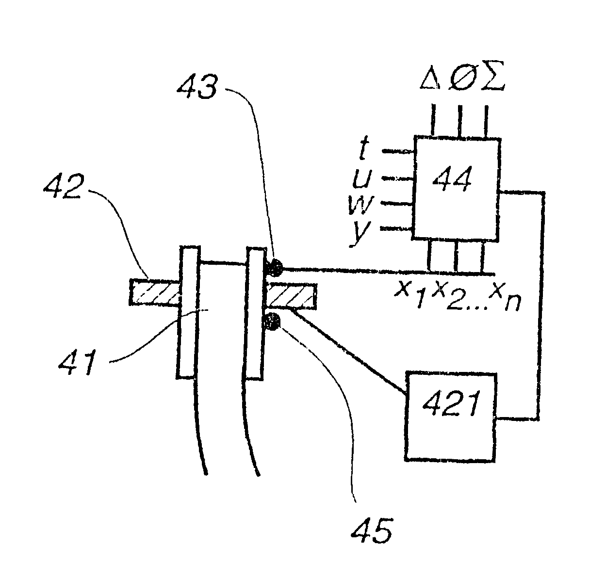
As the flow conditions can vary within the mold, has it in some cases been shown desirable to monitor the flow at two or more locations within the mold and also to apply the magnetic fields in such a way that the magnetic flux density of one magnetic field can be regulated separately and independently of any other magnetic fields based on the flow prevailing in the part of the mold on which the magnetic field is applied to act. The typical situation is that for a slab mold wide two wide sides and a tapping point in the center of the mold, at least one
magnetic circuit is arranged to apply at least one magnetic to act on the melt in each half of the mold, i.e., the mold is, in the casting direction, split into two control zones, each
control zone comprising a half of the mold and is disposed on each side of a plane comprising the center line of the wide sides. The flow at the
meniscus is measured directly or indirectly for both control zones, i.e., mold halves, and the left
control zone sensor is associated with means for regulating the magnetic flux density of a magnetic field acting on the melt in the
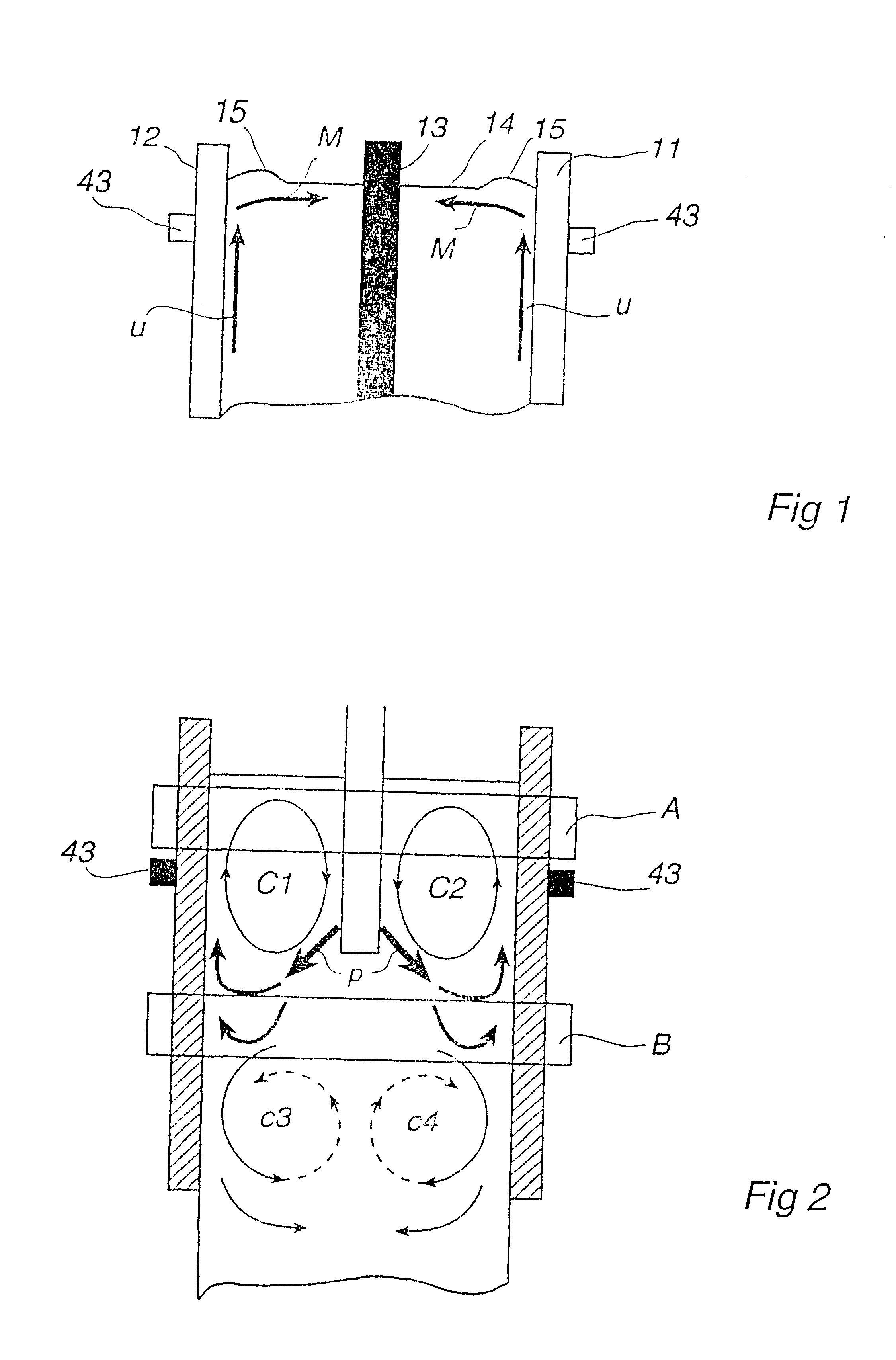
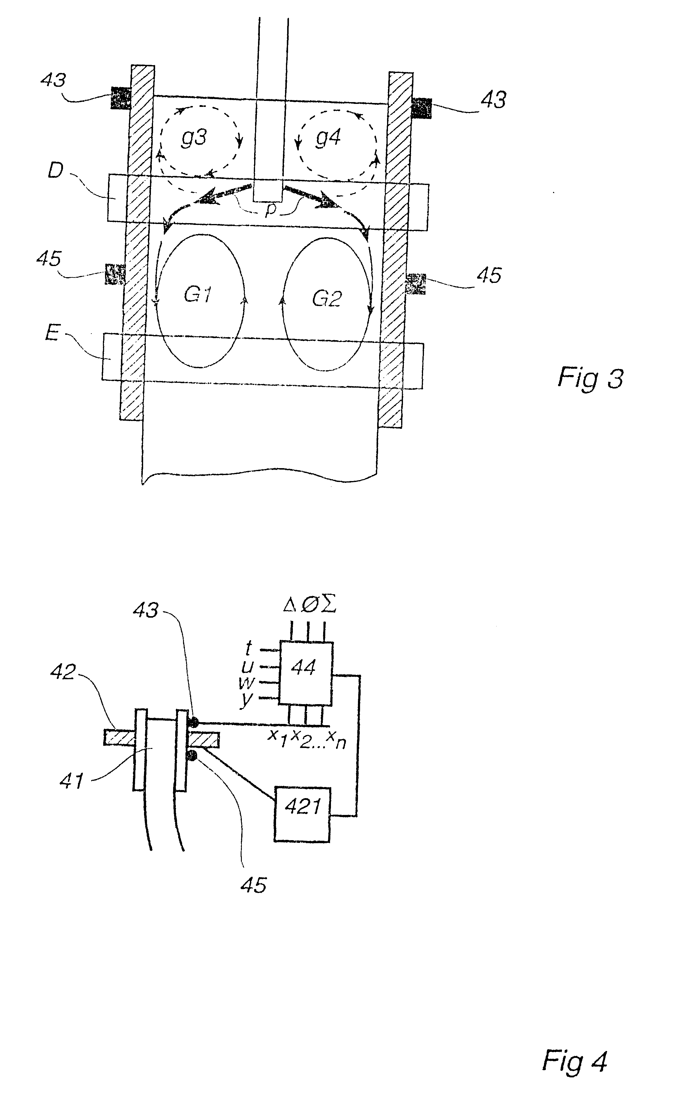
left half of the mold and a right control sensor is associated with means for regulating the magnetic flux density of a magnetic field acting on the melt in the right half of the mold. The mold can, naturally, be divided into zones of any number and shapes where at least one sensor and at least one magnetic flux density-regulating means is associated with each zone. Using two control zones ensures that an essentially symmetrical two-loop flow is developed in the upper part of the mold and that the risks of the two-loop flow developing to an unsymmetrical or unbalanced flow showing, e.g., marked differences in the flow velocities at the
meniscus for the two mold halves, a so called biased flow, or even in the extreme case transforming into an undesired one-loop flow, where the melt flows up along one molds side, across the meniscus to the other side, down and further back across the mold at level with or just downstream the
nozzle ports, is essentially eliminated.
Preferably one or more these parameters is supervised or sampled throughout essentially the whole casting process and included on-line in the
algorithm,
statistical model or method for
data analysis used to evaluate the determined change to the flow and regulate the magnetic flux density of the magnetic field on-line. The changes can be due to a time-dependent process or be due to an induced change of the casting conditions. These parameters which are accommodated for in the
algorithm,
statistical model or method for multivariate data-analysis will thereby effect the on-line regulation of the magnetic flux so that the magnetic flux density can be adopted to these changes and a better control of the secondary flow is accomplished.
According to a further embodiment, the
control unit is also associated to one or more further
electromagnetic devices, which are arranged to apply one or more alternating magnetic fields to act upon the melt in the mold or in the strand. Such electromagnetic device are stirrers which can be arranged to act on the melt in the mold or on the melt down-streams of the mold, e.g., on the last remaining melt in the so called
sump but also high-frequency heaters are used preferably applied to act on the melt adjacent to the meniscus to avoid freezing, melt mold
powder and provide good thermal conditions, e.g., when casting with low superheat.
The present invention according provides means to adopt the flow and thereby also thermal conditions to achieve the desired cast structure while ensuring the cleanliness of the cast product and same or improved productivity. The embodiments which include monitoring or sampling of further parameters and / or information on induced changes in production parameters are especially favorably as they provide the possibility to, upon the detection of a change in a casting parameter, adopt the magnetic flux density to counteract any disturbance like to come as a result of this change or take measures to minimize such a disturbance known to be the result of such change.

