Eureka AIR delivers breakthrough ideas for toughest innovation challenges, trusted by R&D personnel around the world.

Method of making stripped porous polymer films

a technology of porous polymer films and porous polymer films, which is applied in the direction of filtration separation, stationary filtering elements, fuel cells, etc., can solve the problems of affecting the subsequent performance of the film of surfactants in the final product, the surface characteristics of the film may not be easily penetrated by the film, and the disadvantage of the difference in surface characteristics compared to the characteristics of the interior bulk material of some such porous films. to achieve the effect of constant geometry of shearing

Inactive Publication Date: 2002-12-24
BDF IP HLDG
View PDF12 Cites 8 Cited by
  • Summary
  • Abstract
  • Description
  • Claims
  • Application Information

AI Technical Summary

Benefits of technology

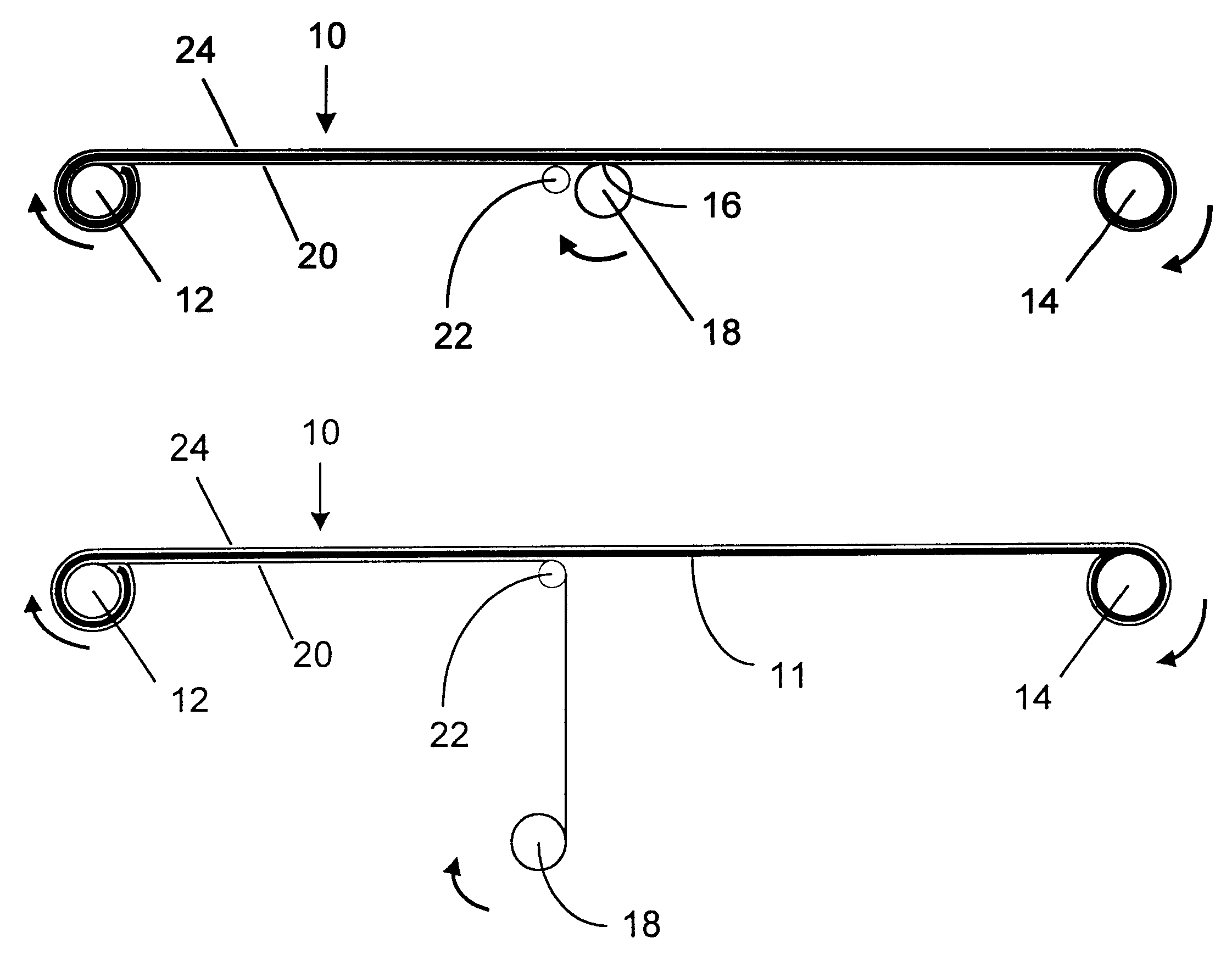
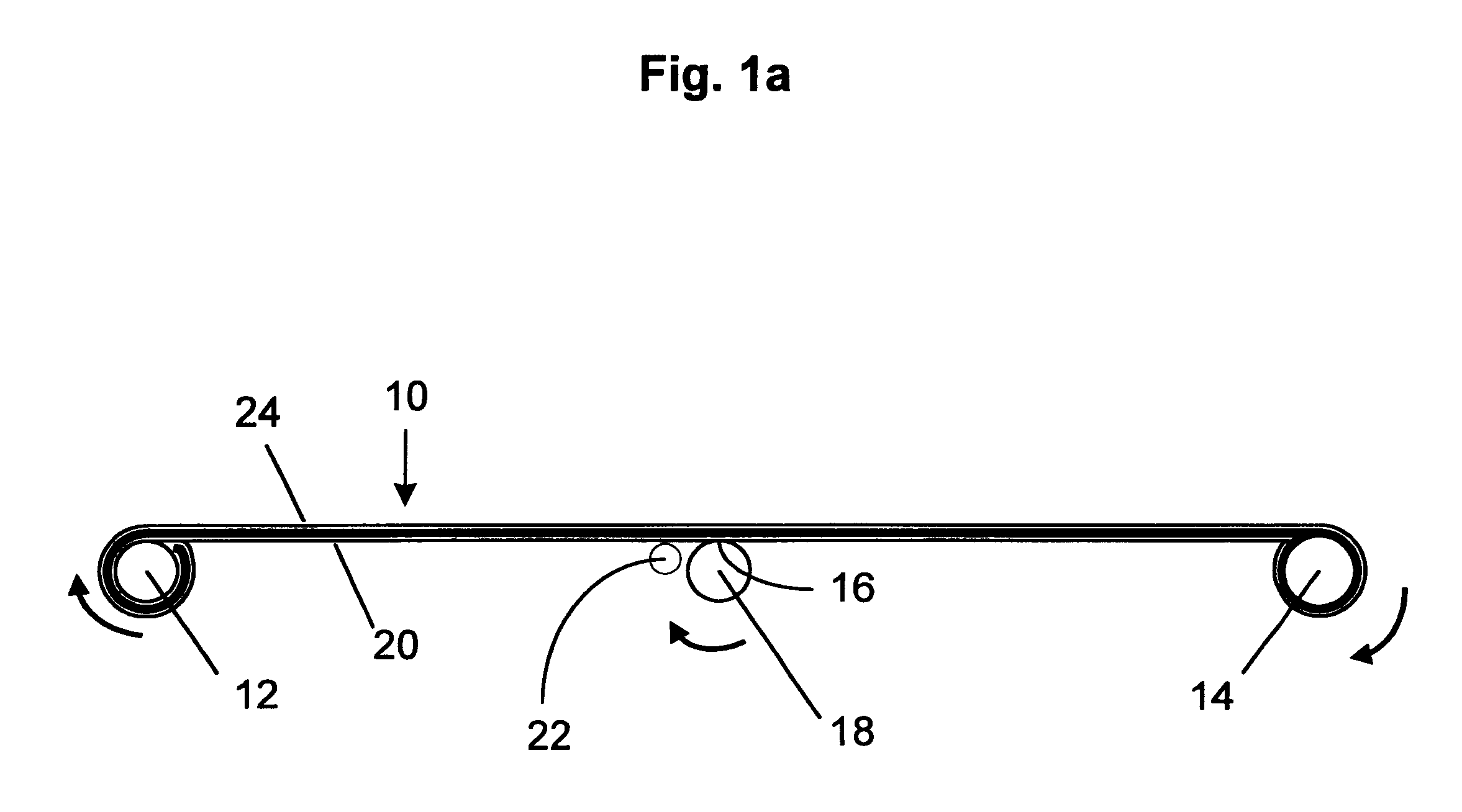
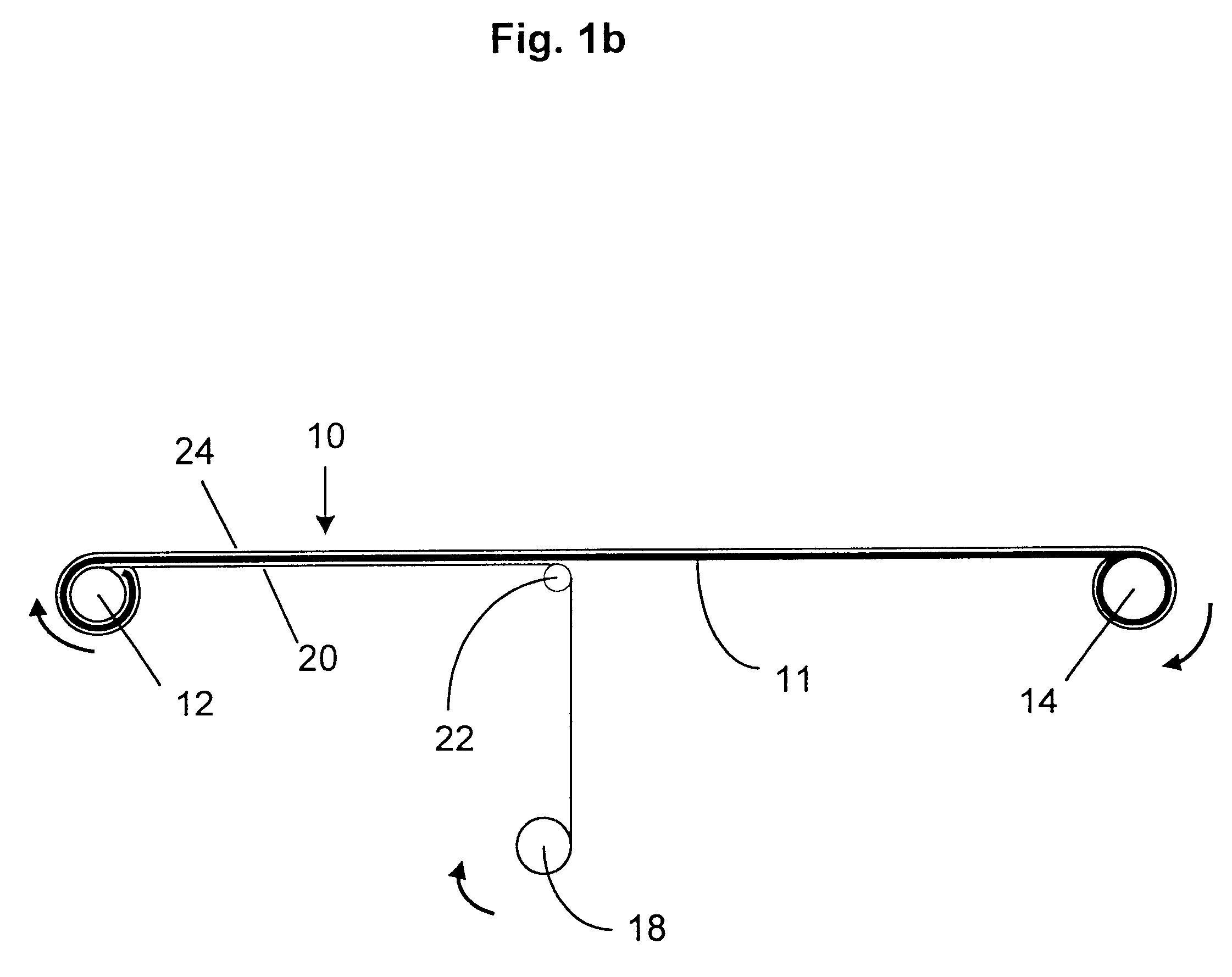
FIGS. 2a and 2b are schematic diagrams of a reel-to-reel type apparatus which may be used for carrying out the described method in which at least portions of surface layers are stripped from both surfaces of a heterogeneous porous polymer film simultaneously. As shown in FIG. 2a, stripped porous polymer film 30 is fed from feed roller 32 to collection roller 34. Anchor 36 on stripping roller 38 attaches to major surface 40 of film 30, and anchor 42 on stripping roller 44 attaches to major surface 46. As film 30 is fed from feed roller 32 to collection roller 34, stripping roller 38 rotates and applies a shearing force to major surface 40 via anchor 46, and stripping roller 44 rotates and applies a shearing force to major surface 46 via anchor 42. As shown in FIG. 2b, stripped porous polymer film 48 is collected on collection roller 34, while at least a portion of the surface layers of major surfaces 40 and 46 are collected on respective stripping rollers 38 and 44. Stripping rollers 38 and 44 may be moved away from film 30 as the amount of material collected thereon increases, as shown in FIG. 2b. As stripping rollers 38 and 44 move away from film 30, guide rollers 48 and 50, respectively, assist in maintaining a substantially constant geometry of the shearing force applied to at least a portion of the surface layer of major surfaces 40 and 46 by respective stripping rollers 38 and 44.
Several tests were then performed comparing the material properties of the starting films and the stripped films of Example 1 and Example 2. The tests showed that the stripped films were substantially homogeneous relative to their respective heterogeneous starting films, having more open pores, reduced surface density, and increased surface roughness. The stripped films also demonstrated increased permeability and penetrability characteristics relative to the starting film.
The rate of transplanar wicking was determined by calculating the percent area increase of the wetted area over the 16-second interval, that is, the size of the wetted area at t=16 seconds was compared to the size of the wetted area at t=0 seconds (when the drop was first applied to the films). Additional spread after 16 seconds was negligible. As indicated in Table 2 below, the stripped microporous films made according to the described method demonstrated significantly improved penetration as compared to the heterogeneous starting films. In addition, the Example 2 material demonstrated superior transplanar wicking relative to the Example 1 material, both before and after stripping. It may be that the difference in rate of transplanar wicking between the materials is due to the increased hydrophilicity and / or porosity of the Example 2 material relative to the Example 1 material. In any event, both materials were amenable to the present method, and the stripped films made thereby exhibited increased air permeability and wetting liquid penetration as compared to the respective starting films.

Problems solved by technology

However, the aforementioned difference in the surface characteristics compared to the characteristics of the interior bulk material of some such porous films can be disadvantageous.
A polymer solution, for example, brought into contact with the surface of the film may not penetrate the film easily, presumably due to surface density characteristics and / or smaller surface pore size.
Surfactant additives have been used to overcome adverse surface interactions with solutions and thereby facilitate penetration, but the presence of surfactants in the final product can be detrimental to subsequent performance of the films, depending upon the application.
Furthermore, the removal of surfactants from the final product can be both difficult and costly.
Such methods can also be costly, however, and may undesirably alter the chemical or structural characteristics of the polymer film surface.
However, the process may be difficult to control and / or reproducibility may be difficult to achieve.

Method used


Image

  • Method of making stripped porous polymer films
  • Method of making stripped porous polymer films
  • Method of making stripped porous polymer films

Examples


example 2

Preparation of Stripped Microporous Polymer Film From Graft-Polymerized Ultra-High Molecular Weight

Polyethylene Microporous Film (Pall GPT10201)

A 152 cm.times.76 cm sample of GPT10201 (trade designation of Pall Corporation) was stripped according to the method described in Example 1. GPT10201 is a microporous UHMWPE material that has been graft polymerized with a polymer to render the material more hydrophilic.

Several tests were then performed comparing the material properties of the starting films and the stripped films of Example 1 and Example 2. The tests showed that the stripped films were substantially homogeneous relative to their respective heterogeneous starting films, having more open pores, reduced surface density, and increased surface roughness. The stripped films also demonstrated increased permeability and penetrability characteristics relative to the starting film.

SEM photomicrographs were taken of the starting film and the stripped film of Example 1. FIGS. 3 and 4 ar...

example 3

Incorporation of Stripped and Unstripped Microporous Polymer Films

Composite Ion Exchange Membranes

In Composite ion exchange membranes were prepared from samples of the starting film and the stripped microporous film prepared by the method described in Example 1 by impregnating each of the samples with the BAM.RTM. 9907147 ionomer solution, as described in U.S. Pat. 5,834,523, and removing the solvent by evaporation at 65.degree. C.

example 4

Use of Composite Ion exchange Membranes In a Fuel Cell

Each of the composite membranes prepared as described in Example 3 were bonded to two platinum-catalyzed carbon fiber paper electrodes at 140.degree. C. under 6700 kPa pressure to form membrane electrode assemblies having a total platinum catalyst loading of 1 mg / cm.sup.2. The resulting membrane assemblies were tested in identical Ballard Mark IV single cell fuel cells operated under substantially identical conditions, namely, 80.degree. C. temperature, 3.02 bar for oxidant and fuel, and 2.0 and 1.5 stoichiometry, respectively, for oxidant and fuel. The voltage at 1 A / cm.sup.2 was measured and the results compared. As indicated in Table 3, the fuel cell containing the composite membrane prepared from the stripped microporous polymer film according to the method described in Example 1 demonstrated significantly higher voltage as compared to the fuel cell containing the composite membrane prepared from the starting film.

In addition...


PUM

PropertyMeasurementUnit
Angleaaaaaaaaaa
Volumeaaaaaaaaaa
Volumeaaaaaaaaaa

Abstract

Stripped porous polymer film and a method for making such film from substantially heterogeneous porous polymer film are described. The heterogeneous film has surface characteristics that are different from the characteristics of the interior bulk material, and the method comprises mechanically stripping at least a portion of at least one surface layer from the heterogeneous film. The stripped porous polymer film may be incorporated into composite membranes. Such composite membranes are particularly suitable for incorporation into membrane electrode assemblies for use in electrochemical cells, including electrochemical fuel cells.

Description

The present invention relates to stripped porous polymer films, as well as methods for preparing such films from substantially heterogeneous porous polymer films.Porous polymer films are used in a wide variety of applications such as liquid and gas filtration, waterproof breathable fabrics, controlled-release systems, batteries, and fuel cells. Such films may be prepared by a variety of methods. For example, microporous polymer films may be made by extruding a solution of a polyalkene into a film, cooling the resulting film to below the gelling point of the solution, then removing the solvent and stretching the solvent-free film in at least one direction. A process of this kind is disclosed in European Patent Publication No. 0378279 A1, in which a solution of polyethylene in decalin is cooled to below the gelling point, the gel is extruded to form a film from which decalin is removed by evaporation, and the resulting film is then stretched in at least one direction to increase its p...

Claims


Application Information

Patent Timeline
IPC IPC(8): B01D67/00H01M8/10
CPCB01D67/0086H01M8/1044H01M8/1046H01M8/1048H01M8/106H01M8/1067H01M8/1081H01M8/1093H01M8/1062Y10T428/31Y02E60/521Y02E60/50Y02P70/50
Inventor STONE, CHARLESSUMMERS, DAVE
Owner BDF IP HLDG
Why Eureka
Eureka Blog
Learn More