Crash prevention in positioning apparatus for use in lithographic projection apparatus

a positioning apparatus and lithographic projection technology, applied in the direction of engine lubrication, liquid/fluent solid measurement, radiation therapy, etc., can solve the problems of unusable whole apparatus, serious effects of any collision between tables, even a low speed on

Inactive Publication Date: 2002-12-24
ASML NETHERLANDS BV
View PDF1 Cites 47 Cited by
  • Summary
  • Abstract
  • Description
  • Claims
  • Application Information

AI Technical Summary

Problems solved by technology

Accordingly, the effects of any collision between tables, even a low speed one, can be very serious.
A major collision causing significant damage to the delicate components of a table may render the whole apparatus unusable due to fractures or permanent deformation of precision parts.
Of course, the software controlling the apparatus can be written to prevent movements of the tables that would bring them into collision but software errors, errors caused by interference or power spikes or unexpected power losses may still lead to collisions.

Method used


Image

  • Crash prevention in positioning apparatus for use in lithographic projection apparatus
  • Crash prevention in positioning apparatus for use in lithographic projection apparatus
  • Crash prevention in positioning apparatus for use in lithographic projection apparatus

Examples


embodiment 1

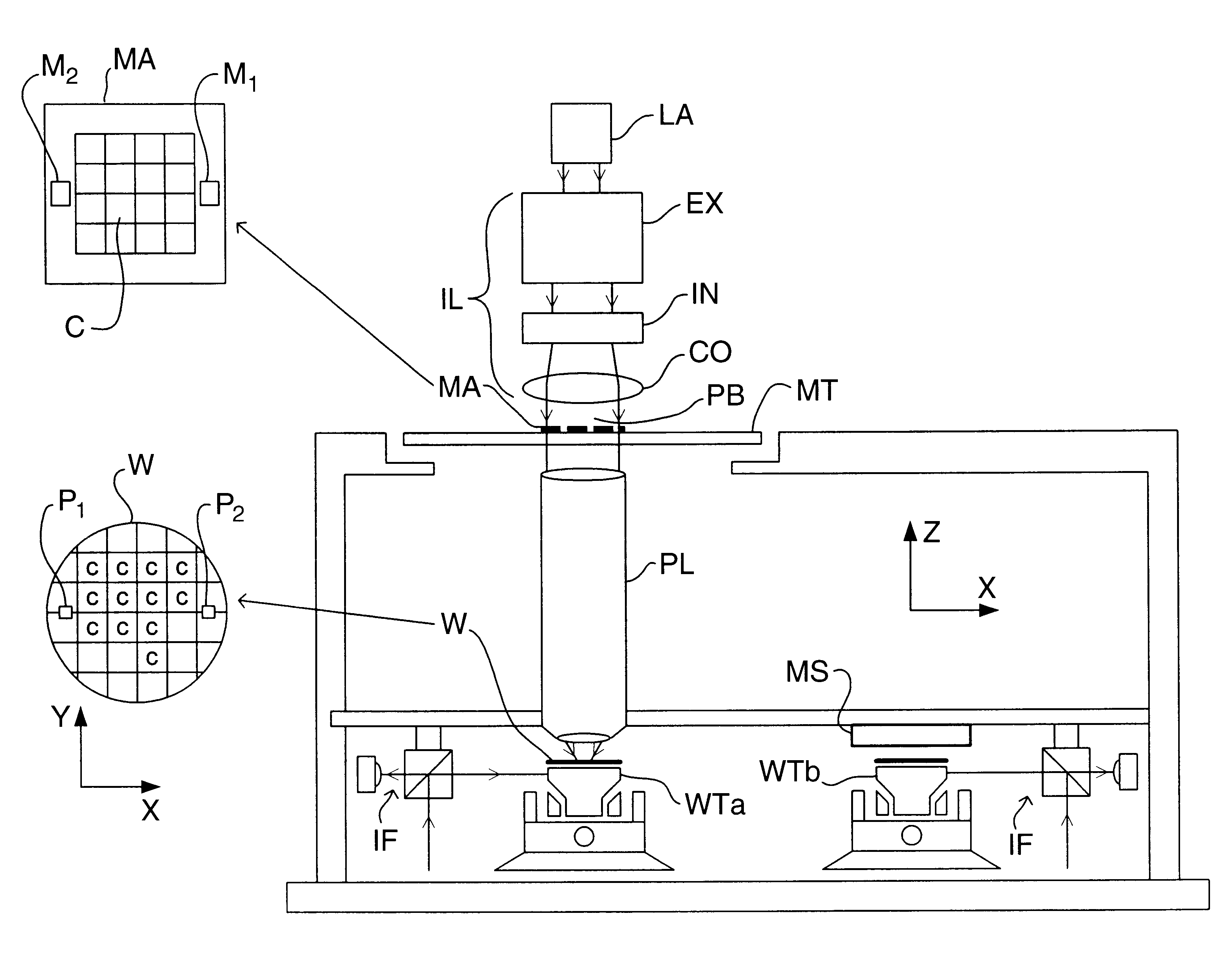
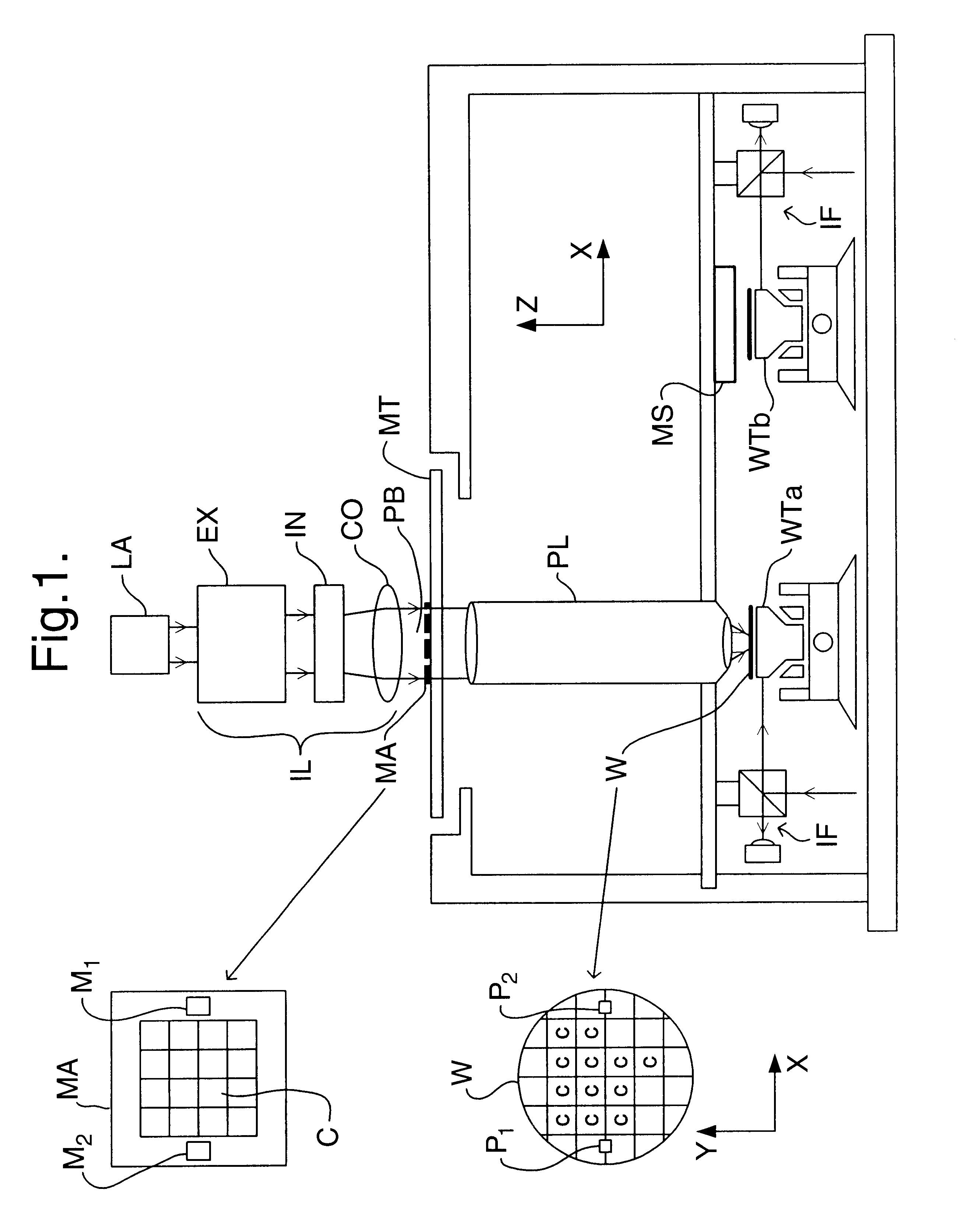
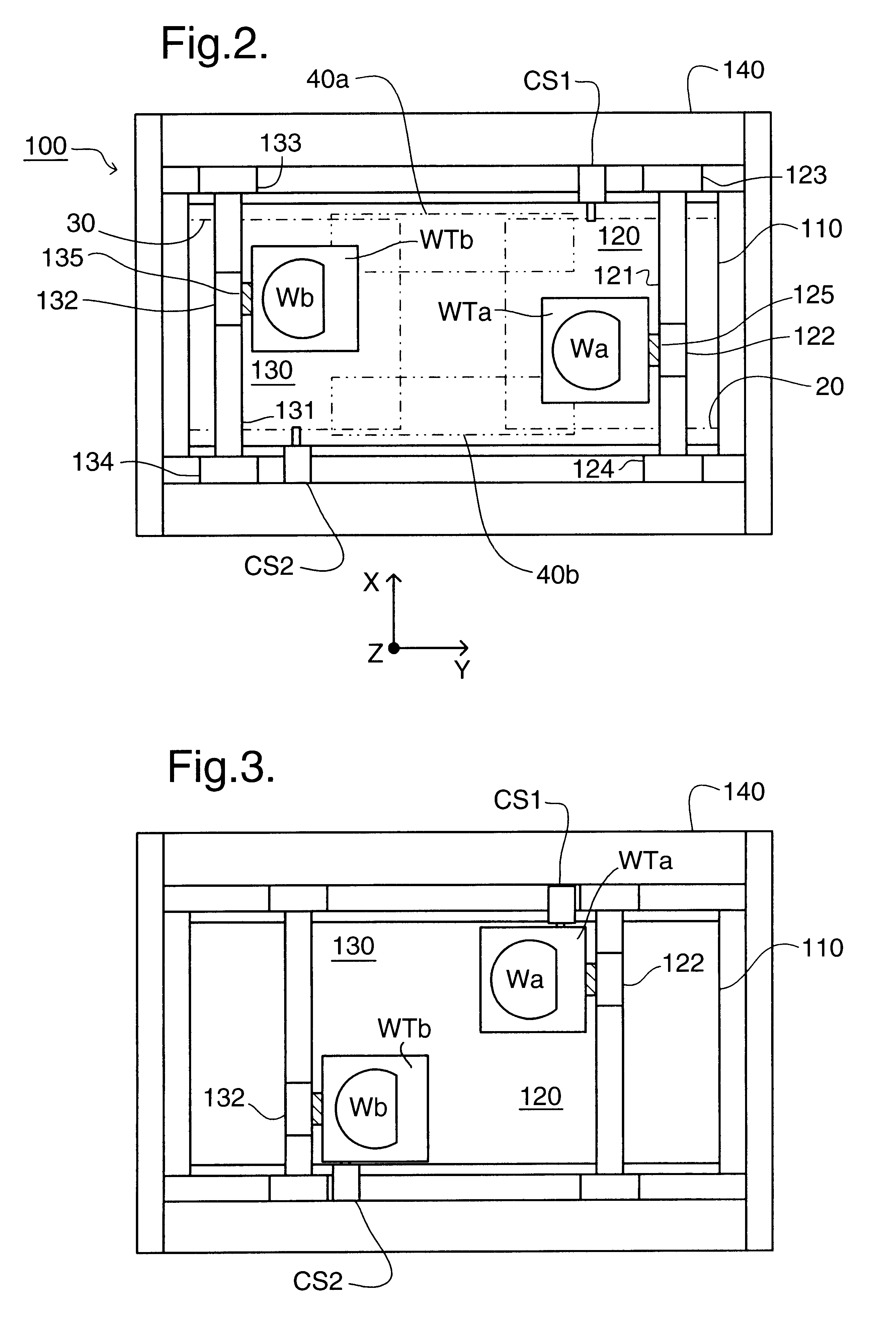
FIG. 2 shows the wafer stage 100 of the lithography apparatus of embodiment 1 in plan. The core of wafer stage 100 is formed by reference table, or stone, 110 which has a flat, level upper surface over which two wafer tables WTa, WTb can move. Wafer tables WTa and WTb are essentially identical and each includes a wafer holder (not shown) for respective wafers Wa, Wb and an air foot (air bearing) to support the table so that it can be moved essentially without friction over the reference table 110. The wafer tables are positioned by two drive units 120, 130, which are of a known H-drive arrangement. Each drive consists of an X-beam 121, 131 on which is mounted the stator of an X-linear motor which drives an X-slider 122, 132 longitudinally of the beam. Wafer tables WTa and WTb are kinematically coupled to respective ones of the X-sliders 122, 132 by releasable stage couplings 125, 135. Each end of each X-beam is mounted on a Y-slider 123, 124, 133, 134 which can be driven by Y-linear...

embodiment 2

A second embodiment of the invention is shown in FIGS. 10 to 13. In this embodiment the possibility of a crash is further reduced by providing the cable shuttles CS1', CS2' with drives so that they, rather than the drive units 120, 130, effect the transfer of the wafer tables between measurement and expose zones.

The first step in the transfer process in the second embodiment is the same as that in the first; the wafer tables WTa, WTb are moved into the labyrinth to engage cable shuttles CS1', CS2' respectively. In the second step, rather than being guided through the labyrinth by the drives 120, 130, coupling mechanisms 125, 135 are released to disengage the wafer tables WTa, WTb from drive units 120, 130. The wafer tables WTa, WTb are then driven through the labyrinth by cable shuttles CS1', CS2', as shown in FIG. 10. The first and second steps in the second embodiment can be carried out "on-the-fly" to reduce the time taken for the transfer. In this arrangement, the wafer tables W...

embodiment 3

In a third embodiment, shown in FIG. 14, the labyrinth arrangement is replaced by a revolving barrier or door 200. Otherwise, the third embodiment may be the same as either the first or second embodiment.

Revolving barrier 200 is mounted on a pivot 201 in the center of the reference table 110. To begin the transfer of wafer tables WTa, WTb, they are driven to diagonally opposite positions either side of pivot 201. The wafer tables WTa, WTb are then driven through the transfer zones 40a, 40b in synchronism with each other and the rotation of the barrier 200. In this embodiment, synchronization of the moving bodies during the transfer process is controlled by software. However, even in the event of a major failure, such as software error, unexpected power loss or interference, the revolving barrier 200 will always be between the two tables WTa, WTb preventing them coming into contact.

In an alternative arrangement the same effect is achieved with retractable barriers; one which projects...


PUM

PropertyMeasurementUnit
wavelengthaaaaaaaaaa

Abstract

In a multi-table lithographic apparatus in which substrate tables may be exchanged between a first working zone where substrates are loaded onto and removed from the table and a second working zones where wafers are exposed, collision prevention means are provided to prevent collisions between tables in the exchange process. The collision prevention means may be formed of a labyrinth or a revolving door. The exchange process may be controlled by shuttles, optionally including drive means, that are interlinked so that the tables can only be exchanged between zones together.

Description

1. Field of the InventionThe present invention relates to crash prevention in positioning apparatus in lithographic projection apparatus comprising:an illumination system for supplying a projection beam of radiation;a first object table for holding patterning means capable of patterning the projection beam according to a desired pattern;a second movable object table for holding a substrate;a third moveable object table for holding second patterning means or a second substrate; anda projection system for imaging the patterned beam onto a target portion of the substrate.2. Description of the Related ArtThe term "patterning means" should be broadly interpreted as referring to means that can be used to endow an incoming radiation beam with a patterned cross-section, corresponding to a pattern that is to be created in a target portion of the substrate; the term "light valve" has also been used in this context. Generally, the said pattern will correspond to a particular functional layer i...

Claims


Application Information

Patent Timeline
Patent Type & Authority Patents(United States)
IPC IPC(8): G03F7/20G03F7/22G03F9/00H01L21/027
CPCG03F7/70716G03F7/70733H01L21/027
Inventor KWAN, YIM BUN P.VAN DE PASCH, ENGELBERTUS A. F.ARIENS, ANDREAS B. G.BUIS, EDWIN J.HOOGKAMP, JAN F.MUNNIG SCHMIDT, ROBERT-HAN
Owner ASML NETHERLANDS BV
Why Eureka
Try Eureka