Air actinism chamber apparatus and method

a technology of air actinism and chamber, which is applied in the direction of material analysis using wave/particle radiation, domestic heating, disinfection, etc., can solve the problems of microorganisms and organic material break down, short-wave x-ray passing through, and longer wave lengths of visible light cannot be achieved

Inactive Publication Date: 2002-12-31
PHASYC
View PDF51 Cites 165 Cited by
  • Summary
  • Abstract
  • Description
  • Claims
  • Application Information

AI Technical Summary

Benefits of technology

FIG. 12 is a top view of the baffle showing the venturi effect created by its insertion into the airstream.
FIG. 1

Problems solved by technology

It is this wavelength difference that results in short-wave x-ray passing through walls, while longer wave lengths of visible light cannot.
Short-wave ultraviolet and x-ray can destroy DNA in living microorganisms and break down organic material while visible light cannot.
With the absence of an electron, organic compounds bec

Method used


Image

  • Air actinism chamber apparatus and method
  • Air actinism chamber apparatus and method
  • Air actinism chamber apparatus and method

Examples


Embodiment Construction

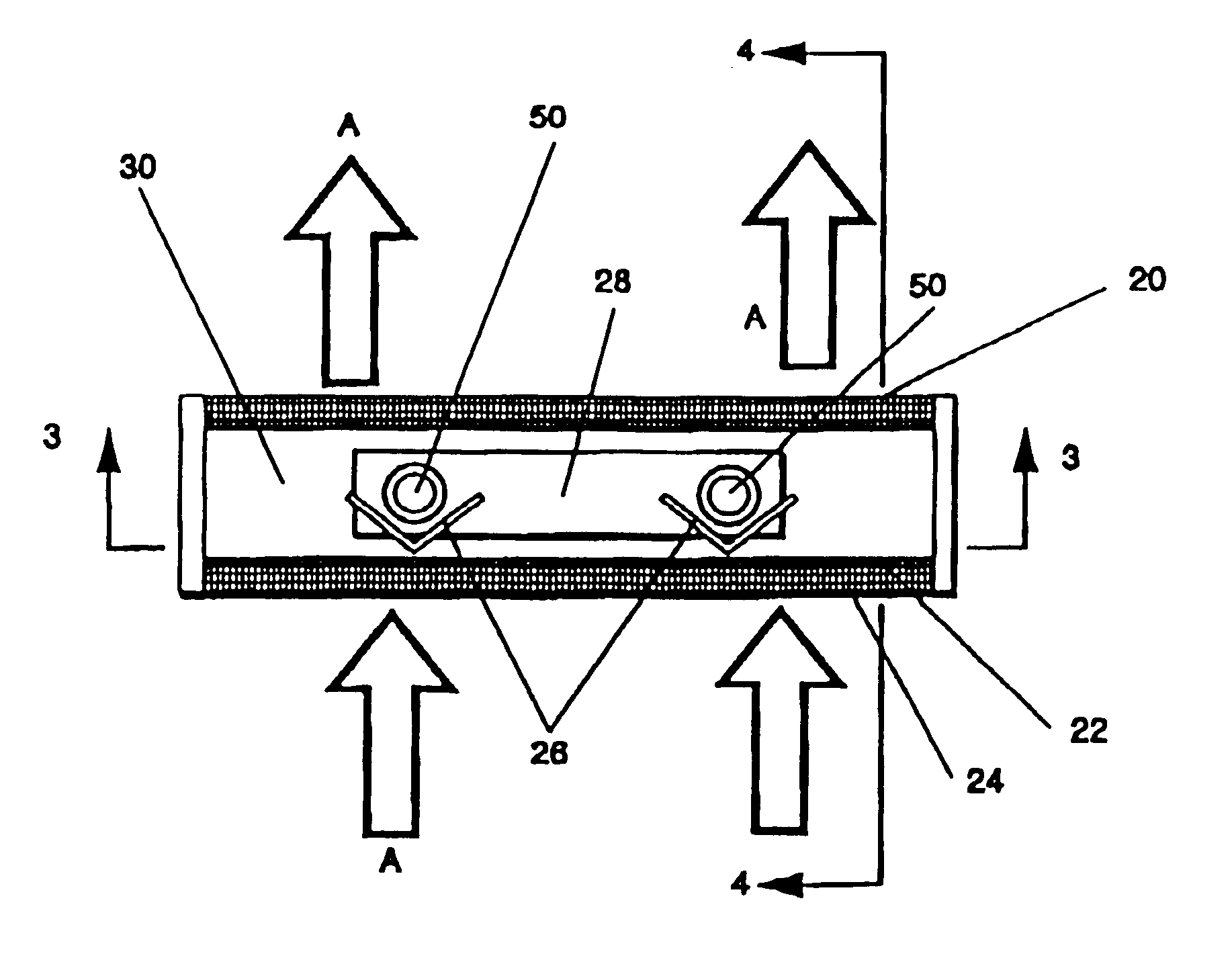
Considering the drawings, wherein like reference numerals denote like parts throughout the various drawing figures, reference numeral 10 is directed to the air actinism chamber according to the present invention.

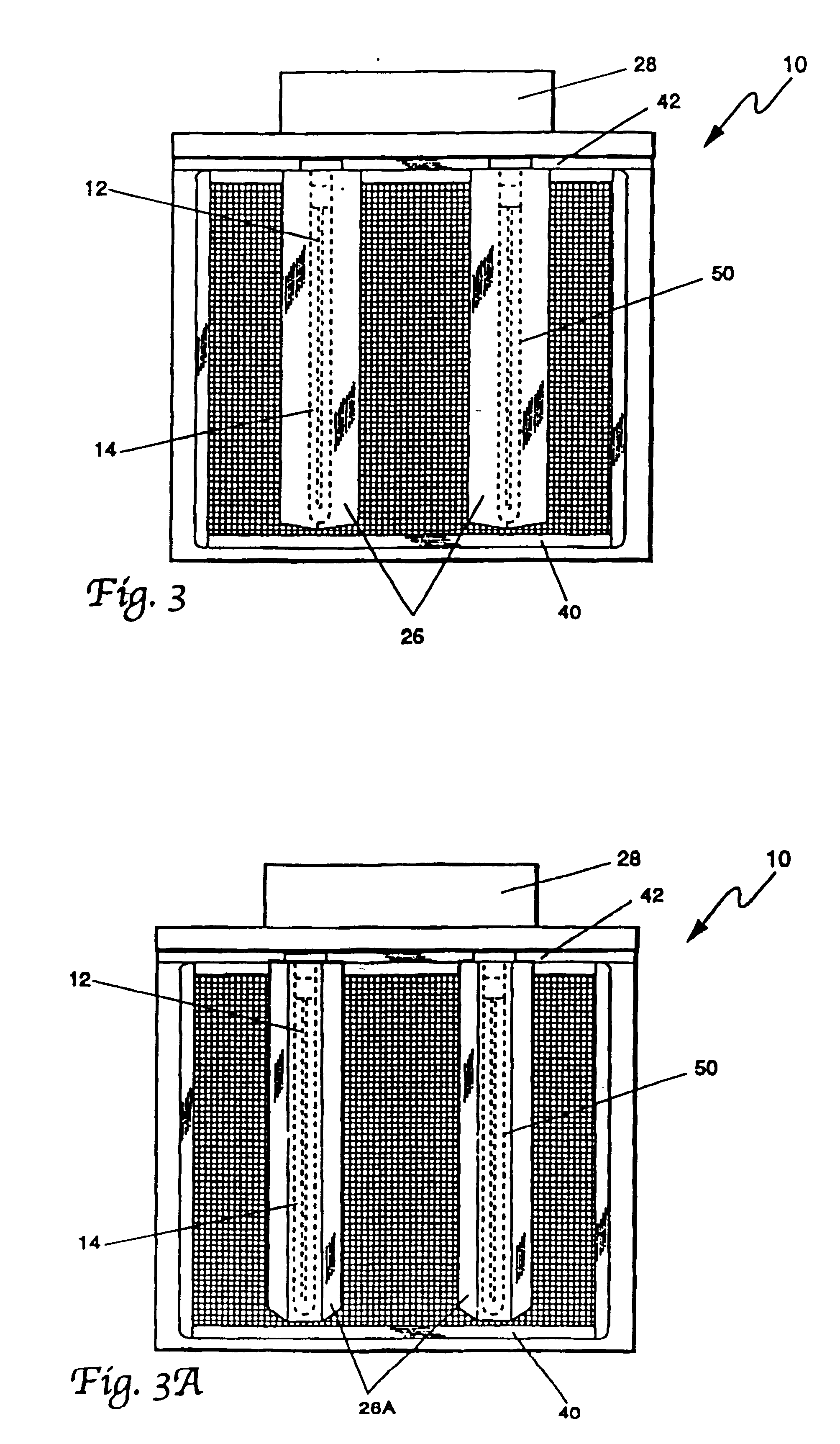
The invention relies on four main components: UV lamp 50, photon chamber 34, baffles 26 or 26A and filters 20. Each component will be described more particularly below.

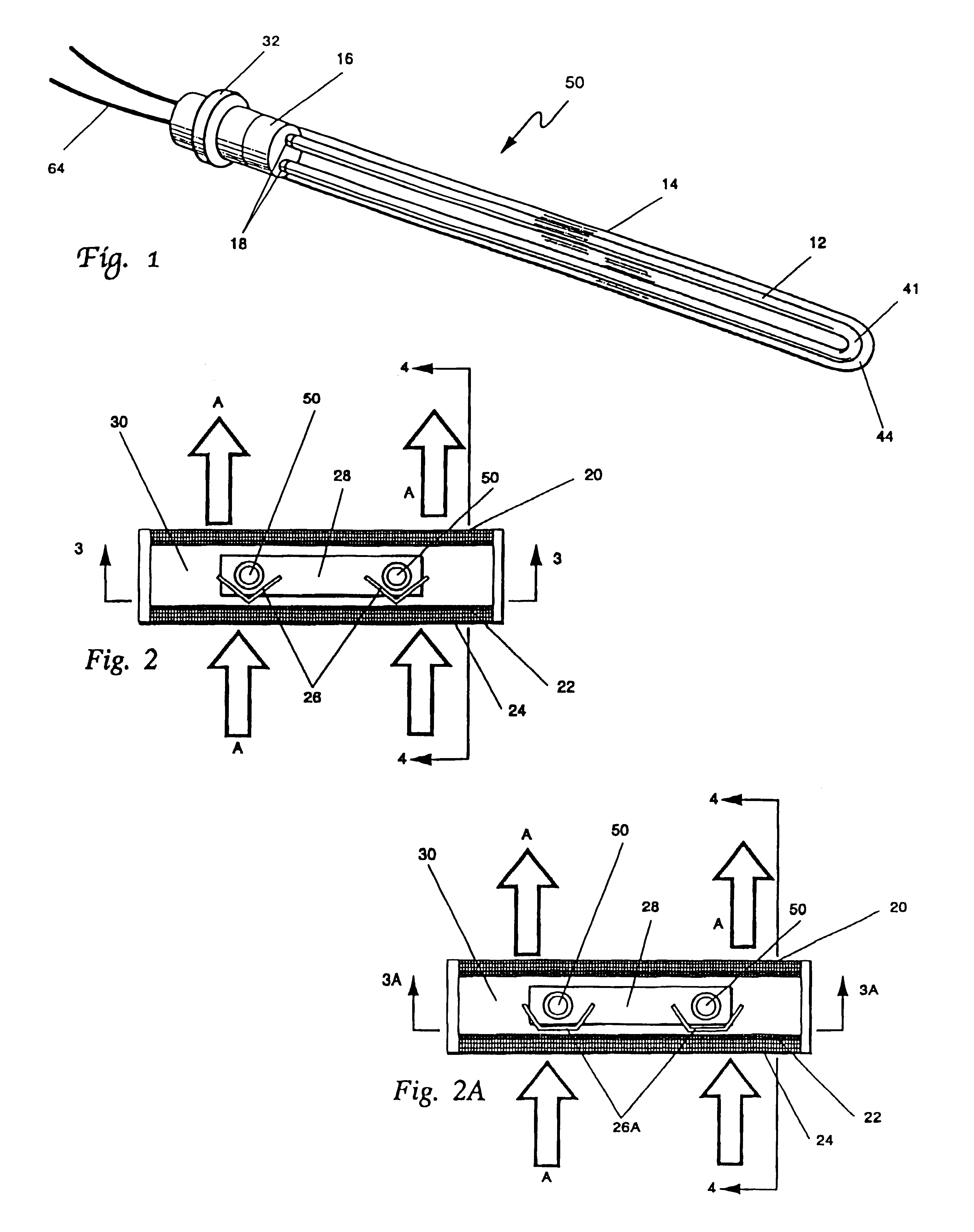
As seen in FIGS. 1 and 8, UV lamp 50 consists of a U-shaped UV quartz, ruby, or sapphire crystal 12 (with quartz being preferred), a quartz sheath 14, lamp coupling overlay 16, lamp base 32, U-shaped bulb gases 41, and lamp gas 44. U-shaped bulb 12 is preferably a quartz glass tube up to fifty inches long that is bent at the center to form a U-shaped bulb filled with one or more of the following: mercury, argon, iron, gallium, xenon or krypton. Aluminum metal or ceramic material is machined for the base 32 of the lamp for holding both the lamp tube 12 and electrode igniters 18. An aluminum coupling 16 allows f...


PUM

PropertyMeasurementUnit
Angleaaaaaaaaaa
Shapeaaaaaaaaaa
Environmental propertiesaaaaaaaaaa

Abstract

An apparatus and method for ultraviolet irradiation of air for the purpose of removing contaminants from that air is disclosed. A U-shaped ultraviolet bulb enshrouded within a quartz tube provides enhanced contaminant destruction characteristics. By combining a plurality of those bulbs in a chamber that is of polished aluminum, and further combining aluminum filters therewith, added irradiation enhancement is achieved. Further provided are baffles or baffling proximate the ultraviolet bulbs that cause the air to go turbulent thus drawing the air closer to the ultraviolet bulb and further enhancing the contaminant destruction characteristics. Moreover disclosed is treatment of substrates with a chemical agent that facilitates the arrest of contaminants from the air onto the substrate for further irradiation of the contaminants from the bulbs. This further irradiation breaks down the arrested contaminants thus providing the substrate with a self-cleansing effect.

Description

This invention relates generally to air cleansing devices. More particularly, this invention relates to ultraviolet (UV) irradiation and filtration devices. In particular, the invention deals with the use of ultraviolet radiation to decompose organic molecules that have a tendency to colonize filters and evaporation coils that are utilized to condition the air in enclosed surroundings. Also, the invention deals with the placement of ultraviolet lamps placed within a chamber that has a means for passing air therethrough. The chamber's walls are polished and as such the UV radiation emitting from the UV lamps is reflected off the chamber walls which results in the decay of organic particles adjacent and within the surround and contained therein. Further, baffles adjacent the UV lamps in the chamber cause turbulence within the air passing therethrough which results in an increase in decay of the organic molecules.Ultraviolet (UV) light in the form of germicidal lamps has been used sinc...

Claims


Application Information

Patent Timeline
IPC IPC(8): B01D39/10B01D39/12A61L9/18A61L9/20
CPCA61L9/20B01D39/12B01D2259/804F24F2003/1667F24F8/22
Inventor BIGELOW, WIL
Owner PHASYC
Why Eureka
Try Eureka