Mapping binary objects in extended relational database management systems with relational registry

a database management system and database technology, applied in the field of relational databases, can solve problems such as severe problems, unmanageable and quick, and extend beyond capabilities, and increase the utilization factor of each row of the data tabl

Inactive Publication Date: 2002-12-31
IBM CORP
View PDF17 Cites 69 Cited by
  • Summary
  • Abstract
  • Description
  • Claims
  • Application Information

AI Technical Summary

Benefits of technology

The invention supports multiple collections of test data, maintains descriptive information for data collections and does not use table columns to store test data. For example, the invention stores chip data in DB2 tables as Binary Large Objects (BLOB's) and maintains descriptive information (meta-data) in separate tables in the database. Additionally, the invention includes a small database footprint and is dynamically extendable without any database table structure changes. With the invention, the database maintenance is reduced while storage is optimized. Any data type, including those beyond the scope of data base management systems (DBMS), can be stored and retrieved with the invention and the database table cardinality is reduced.
The invention is especially useful in environments which involve a large number of diverse products. The invention permits rapid deployment in new areas without having to change the structure of the database.

Problems solved by technology

This quickly becomes unmanageable and extends beyond the capabilities of conventional relational database management systems.
An additional problem of conventional relational database systems is the utilization factor associated with each row of the data table.
This problem becomes severe as products mature and testing is reduced.
In such a conventional system all information about the measurement is carried down from the lot class, which creates a large amount of storage overhead for each test measurement.
However, there are several problems with the conventional relational approach.
First, the database is difficult to change, for example, if the nature of the incoming data exceeds the capabilities of the tables.
Secondly, such a conventional system is very inefficient.
If rows are created that do not use all data columns, as is typical in the semiconductor environment, then space is being wasted.
The conventional relational approach also does not have any capability to distribute the data across multiple databases on multiple physical systems.

Method used


Image

  • Mapping binary objects in extended relational database management systems with relational registry
  • Mapping binary objects in extended relational database management systems with relational registry
  • Mapping binary objects in extended relational database management systems with relational registry

Examples


Embodiment Construction

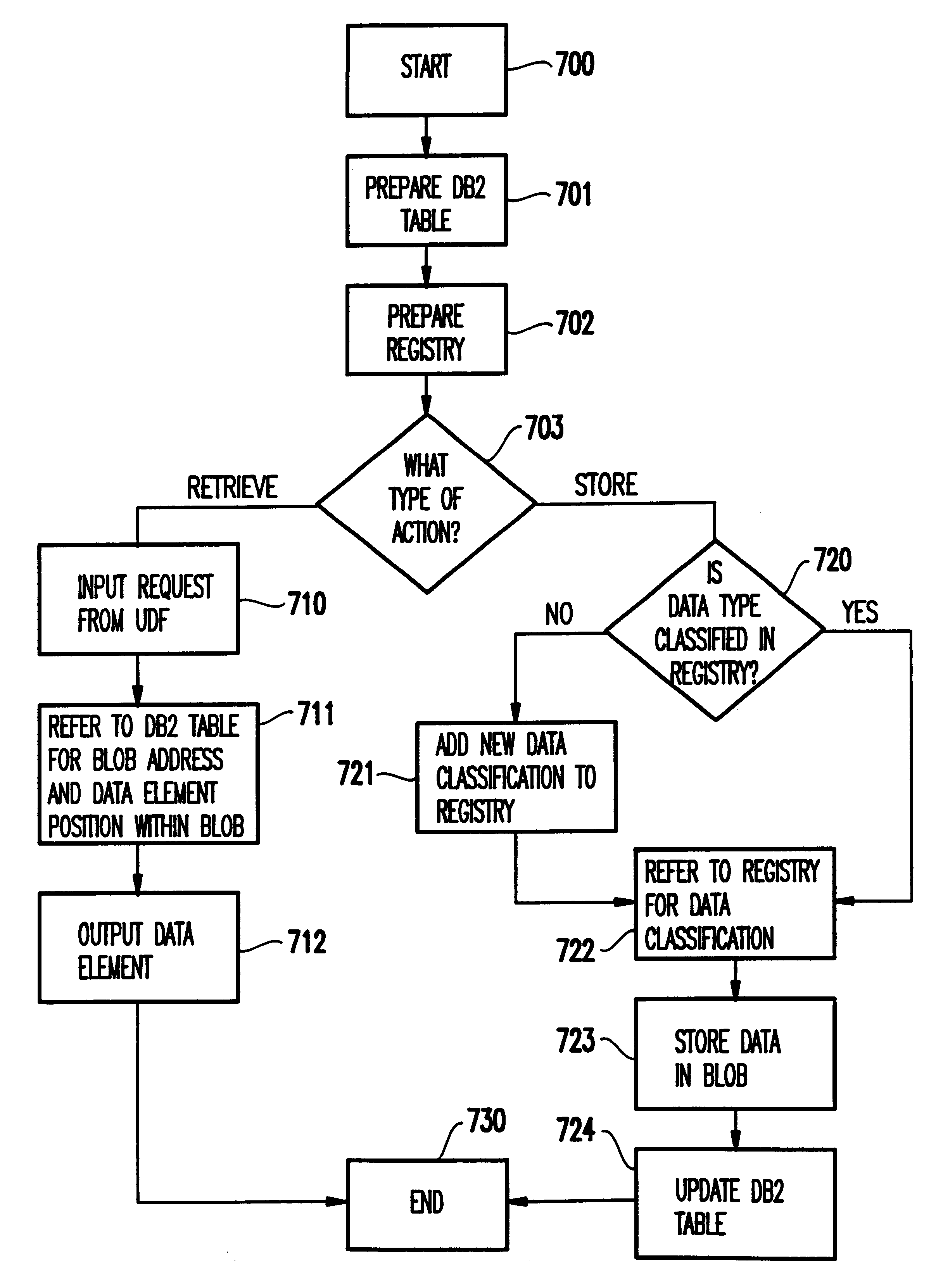
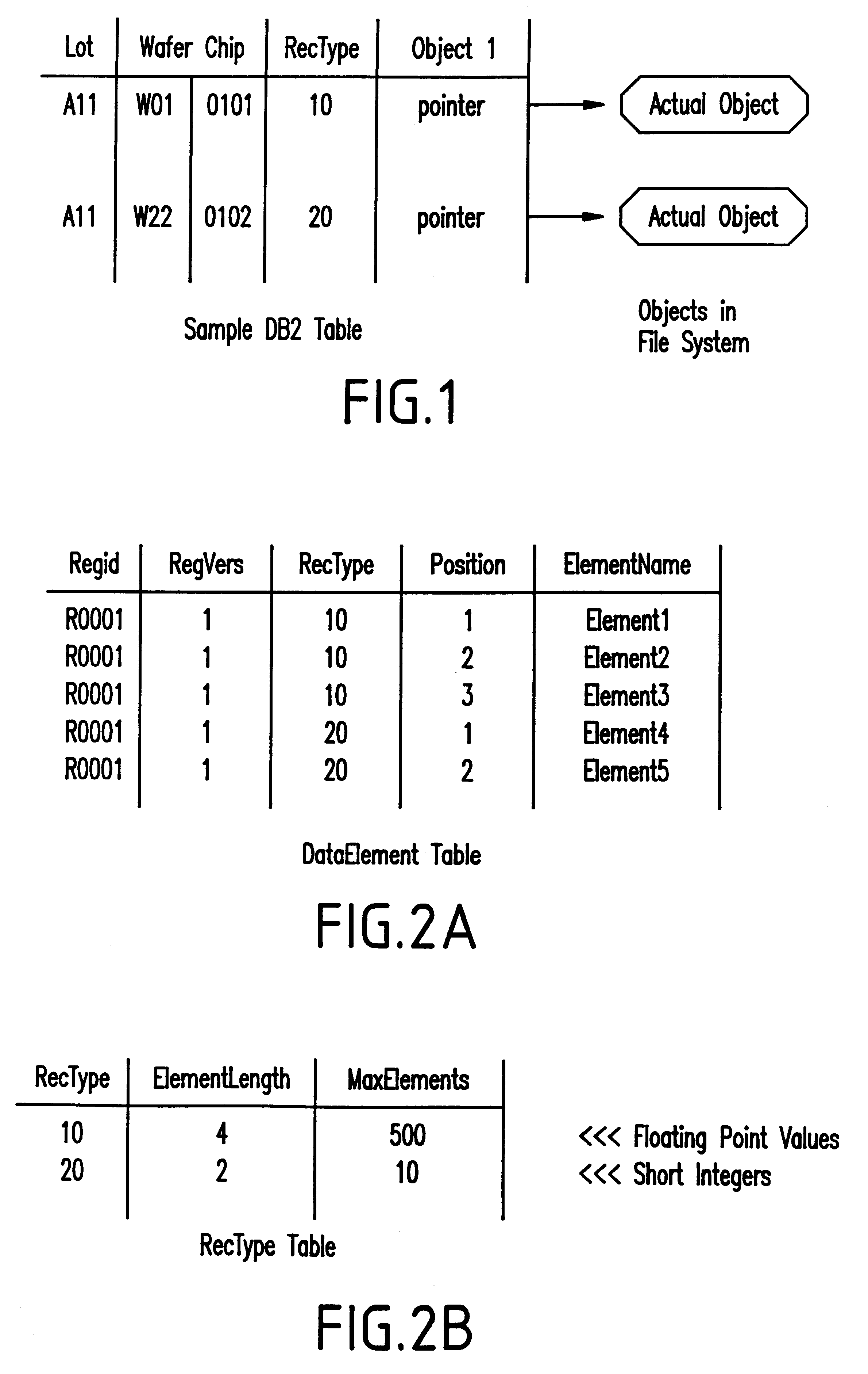
Referring now to the drawings and more particularly to FIG. 1, a sample DB2 table utilizing an inventive Binary Large Object structure (sometimes referred to herein as "BLOB" or "object") is illustrated. The BLOBs extend the conventional relational model discussed above by acting as pure data columns. Unlike conventional columns, the BLOBs do not have any specific size or data type and each BLOB within a given database can have a different size. These columns (or BLOBs) can be of any length, up to an installation maximum size, and, as far as the database manager is concerned, have no form or organization. Thus, with the invention, the database software can determine the structure of the BLOBs for maximum efficiency.

More specifically, the table in FIG. 1 identifies aspects of a semiconductor manufacturing process including the lot identification (Lot), the wafer identification (Wafer) and chip identification (Chip). Further, the table in FIG. 1, identifies the type of record (RecType...


PUM


Abstract

An automated data processing system includes a relational database engine, storage devices having a database table, registry and binary large objects created and updated by the relational database engine and a user defined function engine retrieving data elements stored in the binary large objects. The registry includes data element classifications. The database table includes relational information of the data elements, the data element classifications and pointers to the binary large objects, and the relational database engine creates and updates the binary large objects based on the database table and the registry.

Description

1. Field of the InventionThe present invention generally relates to databases and more particularly to a relational database which utilizes binary large objects and an object registry table in lieu of conventional data columns.2. Description of the Related ArtDatabases are highly useful for organizing many types of information. For example, production items can be tested and the test information stored in a database. The semiconductor manufacturing environment is characterized by numerous part numbers running in the fabricator at the same time. While all of these parts typically belong to the same product technology group, they all differ in some way. This leads to the need for different test requirements for all products.Conventional systems have different test requirements that translate into different storage requirements for a database system. More specifically, one product may test N parameters while another tests M parameters. The situation becomes more complex when the conten...

Claims


Application Information

Patent Timeline
Patent Type & Authority Patents(United States)
IPC IPC(8): G06F17/30
CPCG06F17/30318Y10S707/99931Y10S707/99952G06F16/2219
Inventor PRATT, ROBERT C.
Owner IBM CORP
Why Eureka
Try Eureka