Apparatus for power generation with low drag rotor and ramjet assembly

a technology of ramjet and rotor, which is applied in the direction of reaction engines, machines/engines, liquid fuel engines, etc., can solve the problems of ramjets not being used in commercial power plants for electricity production, reducing overall efficiency, etc., and achieves the effects of convenient construction, service, and high efficiency ra

Inactive Publication Date: 2003-01-28
DRESSER RAND CO
View PDF56 Cites 34 Cited by
  • Summary
  • Abstract
  • Description
  • Claims
  • Application Information

AI Technical Summary

Benefits of technology

allow the generation of power to be done in a simple, direct manner;
Another feature of the present invention is the use of a monofilament carbon fiber winding as an integral part of the structure of the rotor, which provides the advantage of high strength, thus enabling operation at rotational speeds above stress failure limits of conventional materials such as steel and titanium.

Problems solved by technology

However, insofar as I am aware, ramjets have not been employed in commercial power plants for production of electricity.
Also, it is important that a power plant avoid large parasitic losses that undesirably consume fuel and reduce overall efficiency.

Method used


Image

  • Apparatus for power generation with low drag rotor and ramjet assembly
  • Apparatus for power generation with low drag rotor and ramjet assembly
  • Apparatus for power generation with low drag rotor and ramjet assembly

Examples


Embodiment Construction

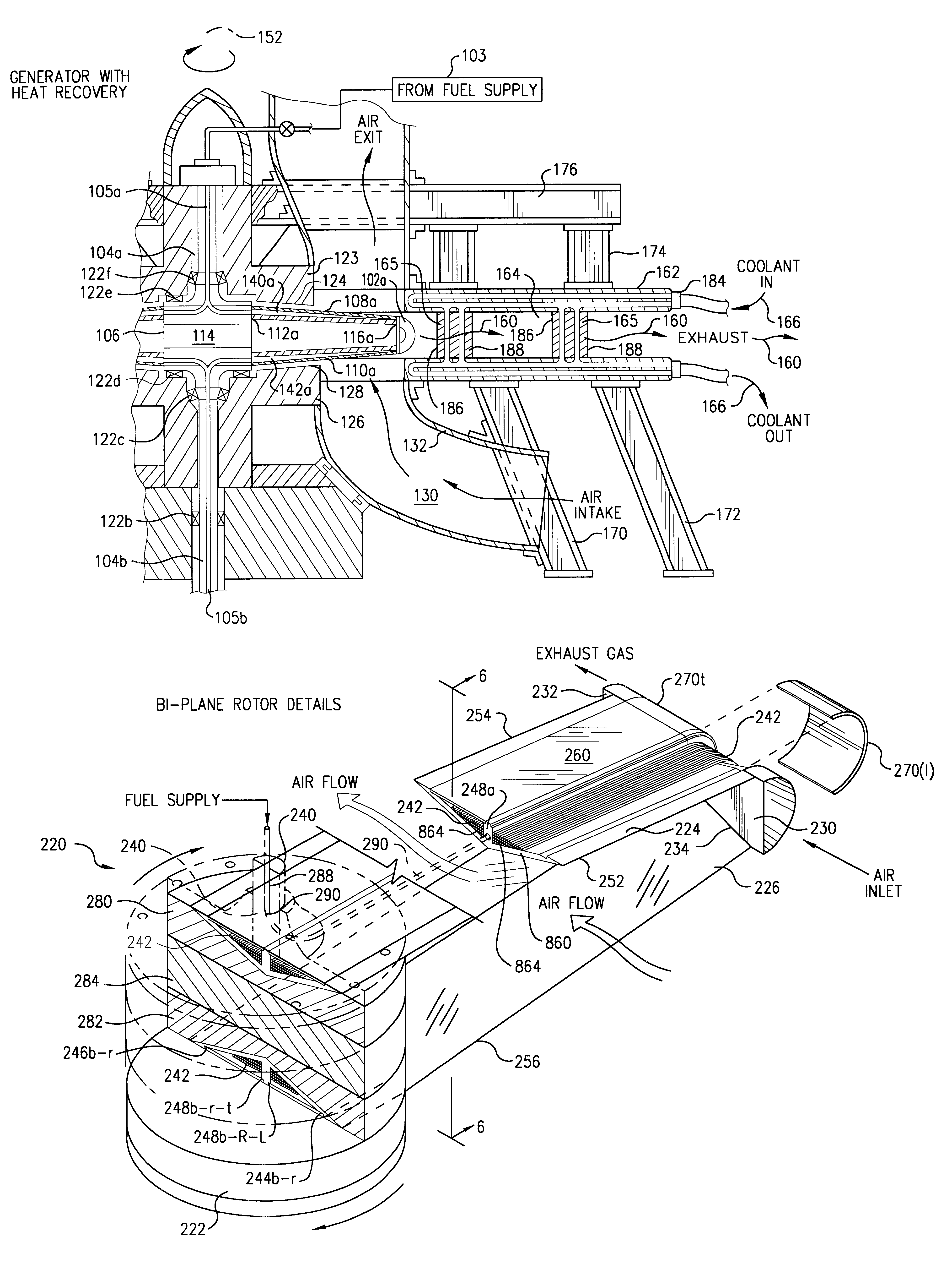
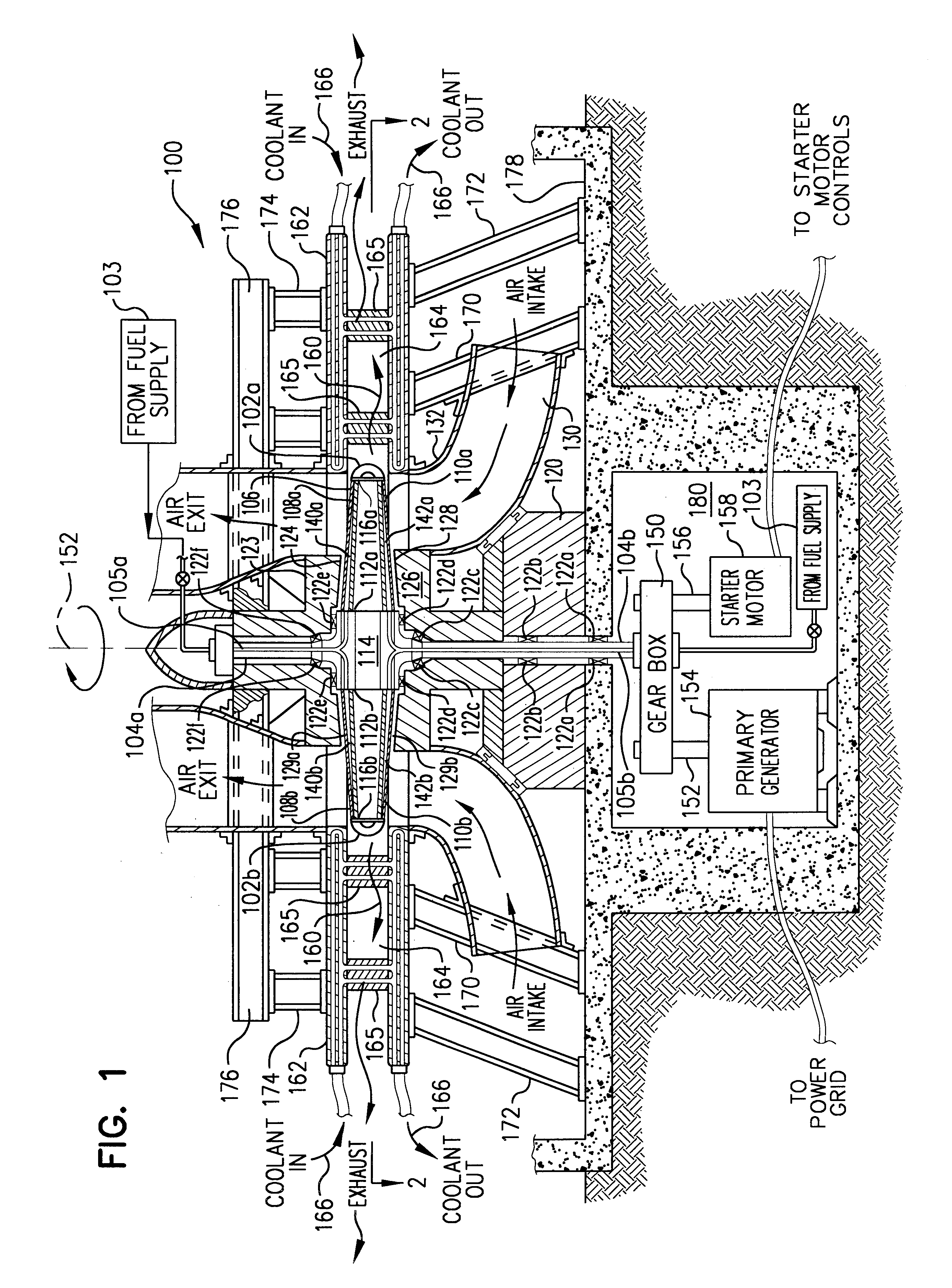
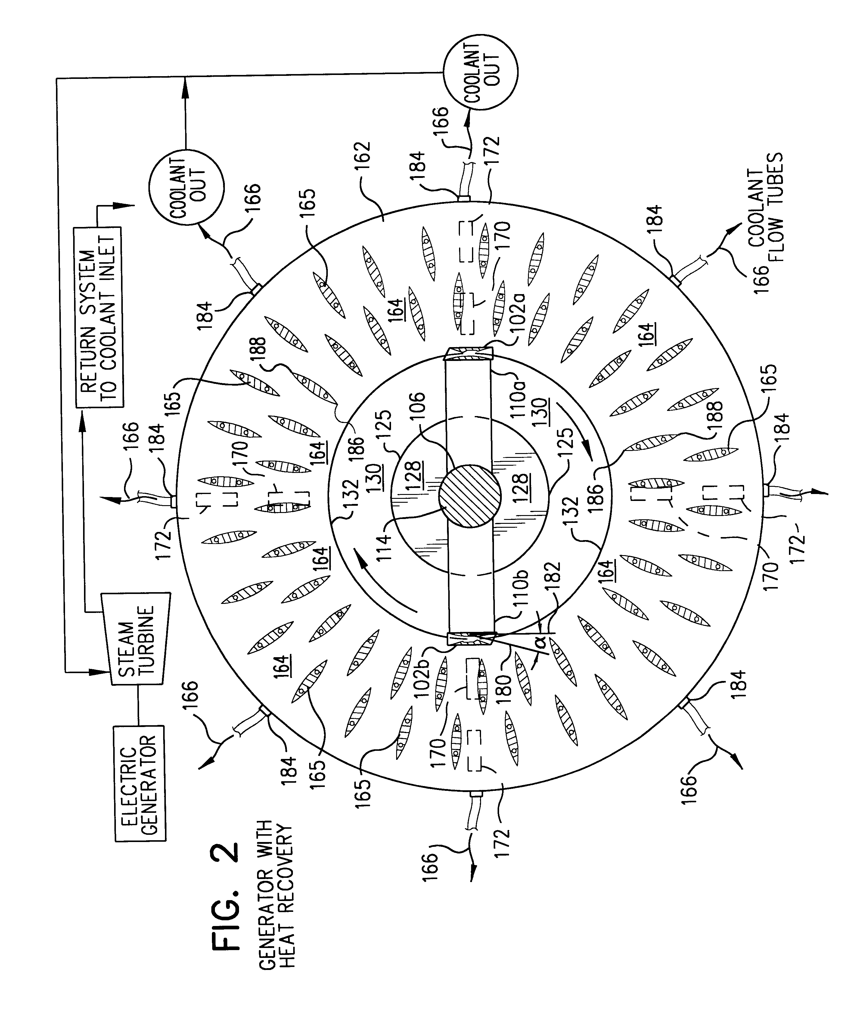
The invention will be better understood and appreciated from consideration of a preferred embodiment thereof which, for purposes of descriptive clarity, includes simply a power plant with heat recovery type exhaust gas cooling. It is of course appreciated that additional features and combinations with other power generation apparatus may be desirable in particular circumstances. However, the power plant system to be initially described below will be a basic building block in most instances of a power plant design due to the desirability of capturing thermal energy from combustion gases.

My power plant is based on high speed, supersonic propulsion phenomenon which allows the elimination of most moving parts which are common in other types of combustion power plants currently available. Simplification of the power generation apparatus allows initial capital costs to be minimized, and the superb system performance allows operating costs to be minimized.

Basic Power Plant

Referring now to ...


PUM


Abstract

An apparatus (100) for generation of mechanical and electrical power. Ramjet type thrust modules (102a, 102b) operate at supersonic speeds (preferably Mach 3 to 4) at the distal or tip ends (116a, 116b) of a low aerodynamic drag rotor (106). Rotor (106) is affixed at a hub means (114) to a power output means including central rotating upper (104a) and lower (104b) shaft portions. Rotor (106) is a structural member which transmits the thrust generated by the thrust modules (102a, 102b) to the shaft portions (104a, 104b). The ramjet thrust modules (102a, 102b) capture and compress a supplied free air stream, which is mixed with and oxidizes a convenient liquid or gaseous fuel such as natural gas from fuel supply means (103). Combustion gases expand to create thrust to rotate the thrust modules (102a, 102b), which are constrained by the rotor (106), to rotates about the axis defined by the shaft (104a, 104b) at supersonic thrust module velocities, producing shaft energy. Escaping exhaust gases (160) may be cooled by passing them through an enthalpy extraction section (162) to heat a secondary heat transfer fluid (166). If the secondary heat transfer fluid (166) is water, the steam may be used directly for its thermal energy, or the steam sent to a steam turbine to produce additional shaft energy. Combustion gases (160) may also be directed through a reaction turbine (1002) to utilize remaining kinetic energy to generate shaft energy. The apparatus and method is particularly useful for generation of electrical and mechanical power at substantially improved efficiency rates when compared to conventional, prior art power plants.

Description

A portion of the disclosure of this patent document contains material which is subject to copyright protection. The owner has no objection to the facsimile reproduction by anyone of the patent document or the patent disclosure, as it appears in the Patent and Trademark Office patent file or records, but otherwise to reserves all copyright rights whatsoever.My invention relates to a novel, revolutionary apparatus and method for the generation of electrical and Mechanical power. More particularly, my invention relates to a power plant driven by thrust modules, which are preferably ramjet engines, and to novel rotors designed to withstand the extremely high tensile stress encountered while rotatably securing such thrust modules. The rotors are design ed for operation at supersonic tip speeds while maintaining low aerodynamic drag, and are constructed of composite carbon fiber and / or metal matrix composites. Power plants of that character are particularly useful for generation of electr...

Claims


Application Information

Patent Timeline
Patent Type & Authority Patents(United States)
IPC IPC(8): F02C3/00F02K7/00F02C3/16
CPCF02C3/165F02K7/005Y02T50/672Y02T50/67Y02E20/16Y02T50/60
Inventor LAWLOR, SHAWN P.
Owner DRESSER RAND CO
Why Eureka
Try Eureka