Plasma torch cartridge and plasma torch equipped therewith

a technology of plasma torch and cartridge, which is applied in the direction of gas-filled discharge tubes, manufacturing tools, solventing apparatus, etc., can solve the problems of electrode wear and tear, and put the electrodes at a serious disadvantag

Inactive Publication Date: 2003-02-04
COMMISSARIAT A LENERGIE ATOMIQUE ET AUX ENERGIES ALTERNATIVES
View PDF8 Cites 25 Cited by
  • Summary
  • Abstract
  • Description
  • Claims
  • Application Information

AI Technical Summary

Benefits of technology

In a hostile environment (radioactive, being compelled to work in a glove box or in the remote manipulator), the work must be simplified as far as possible. The standard exchange of sub-units is often preferable to the dismantling and to the re-assembly of isolated parts in a complex unit. The intervention time is shorter, the reliability of a new and inspected sub-unit is much better than that of a dismantled and re-assembled complex unit.
In this way the plasmagene gas circuit is made with a single auxiliary part, the centering device, by a simple operation carried out under pressure to push along an axial direction a centering device tightened on the cathode in the axial cavity of the anode. With the tightening of the centering device in the anode and on the cathode assembly of the anode, cathode unit is completed. This assembly of the anode on the cathode constitutes moreover a part of the plasmagene gas distribution circuit. In the preferred embodiment continuity and regularity of gas distribution is ensured given that the relay between the centering device conduits and the gas inflow conduits through the anode is provided by an annular distribution volume. The annular distribution volume is constituted, by a radial groove, which may be located either on the anode, or on the centering device, or again both on the anode and on the centering device. In this way the cartridge according to the invention does not require to supply gas any joint or conduit, other than those made by piercing or machining or molding, in the parts required for the torch to operate. As far as assembly is concerned, using a connecting groove between the centering device conduits and the gas inflow conduits through the anode, simplifies assembly since it is not then necessary to index angularly the anode and the centering device.

Problems solved by technology

Wear and tear on the electrodes puts them therefore at a serious disadvantage.

Method used


Image

  • Plasma torch cartridge and plasma torch equipped therewith
  • Plasma torch cartridge and plasma torch equipped therewith
  • Plasma torch cartridge and plasma torch equipped therewith

Examples


Embodiment Construction

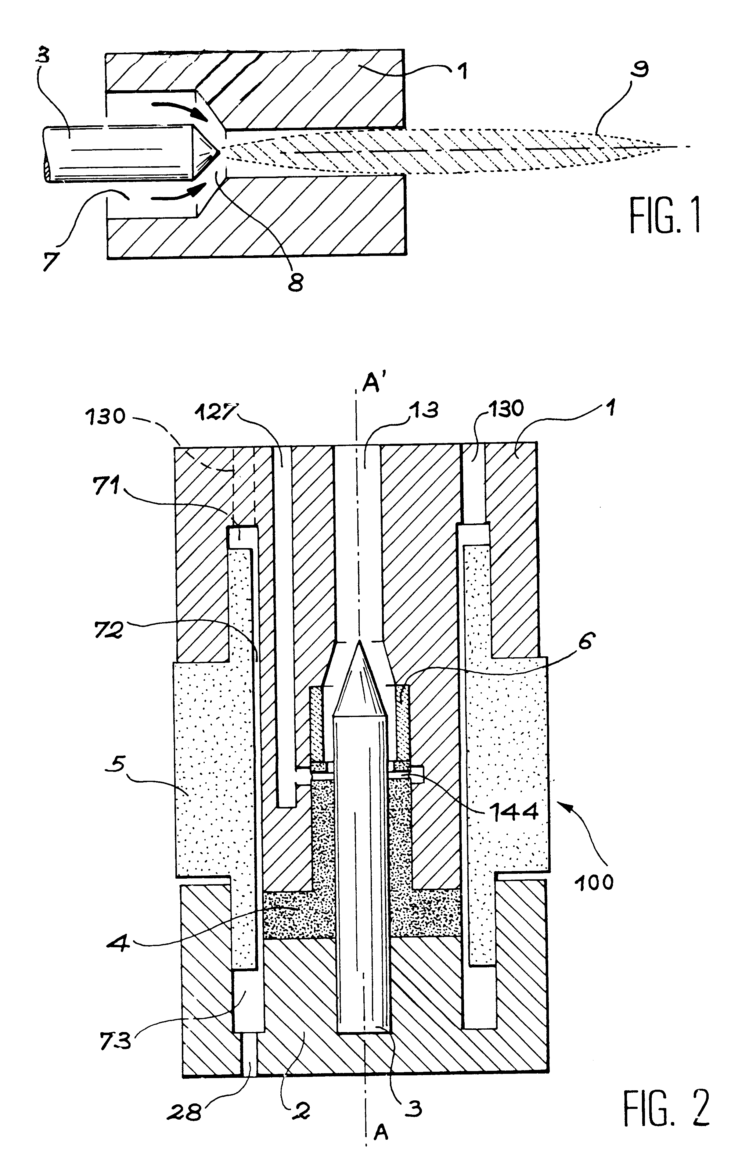
A cartridge example 100 according to the invention will now be described in conjunction with FIG. 2. In this embodiment example, the cartridge 100, and the parts of which it consists, have forms with a symmetry of revolution around an axis AA' constituting the axis of the cartridge.

The parts, which, when assembled, together constitute a cartridge 100 according to the invention, are 6 in number. These are:

an anode nozzle made of electrolytic copper 1

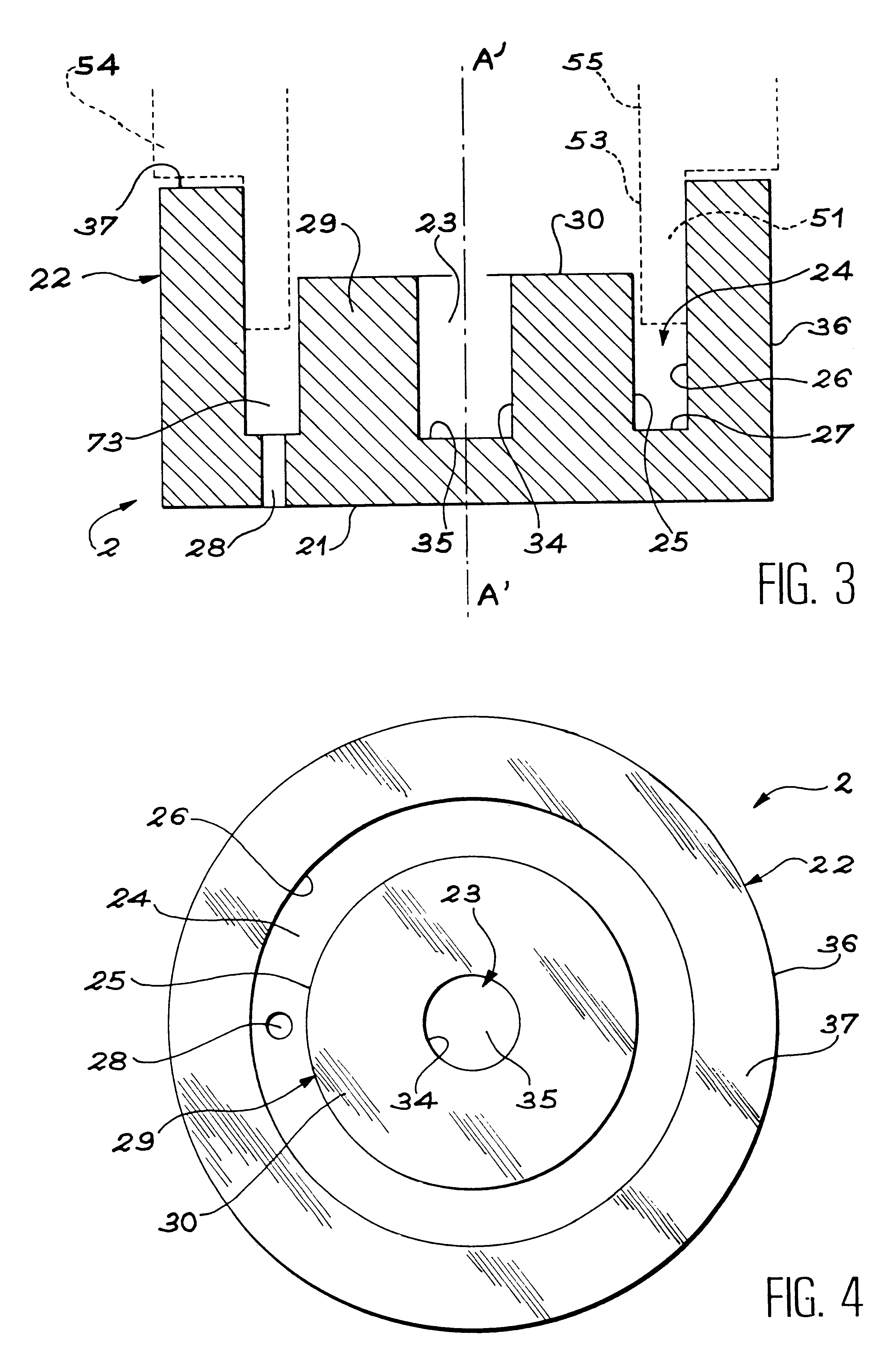
a cathode support made of electrolytic copper 2

a doped tungsten cathode 3

a cathode centering diffuser device made of plastic material 4

an assembler made of plastic material 5

a ceramic insert 6.

an assembler made of plastic material 5

a ceramic insert 6.

When they are assembled, parts 1 to 6 provide between them in a known way and as shown in FIG. 1, a gas circulation channel 7, an inter electrode space where an arc 8 can be created. The plasma 9, (not shown in FIG. 2), is ejected by a nozzle 13 of the anode 1.

Each of these parts and their mo...


PUM

PropertyMeasurementUnit
temperaturesaaaaaaaaaa
poweraaaaaaaaaa
outer diameteraaaaaaaaaa

Abstract

The invention concerns a plasma torch comprising an interchangeable cartridge (100) consisting of six components only: an electroplating copper anode nozzle (1); an electroplating cathode support (2); a doped tungsten cathode (3); a plastic cathode diffusing-centring device (4); a plastic assembling device (5); a ceramic insert (6). Said components are assembled by pressing and the assembly of the components form volumes (71, 72, 73) constituting the anode cooling circuit and the plasma forming gas intake conduits (127, 44). The intake and discharge of fluid are provided by a connecting and maintaining structure designed for the easy mounting of the cartridge (100).

Description

The invention is located in the field of plasma torches.PRIOR ARTArc plasmas belong to the family of thermic plasmas. They are partially ionised gaseous media, conductive of electricity but by and large electrically neutral, at pressures in the region of atmospheric pressure. They are generated by means of a plasma torch, by passing one or more plasmagene gases through an electric arc which is maintained between two electrodes.To bring gases to a high temperature and high specific enthalpy, blown arc torches are used. This means that the arc is confined to the inside of the torch containing the two electrodes and it is the high speed jet of high temperature gas (the plasma) which is used in the process.FIG. 1 shows in a very diagrammatic way the principle of such a torch. A torch of this kind includes two electrodes, an anode 1 and a cathode 3, concentric with each other and providing between them a gas circulation channel 7.The two electrodes 1, 3 are connected to a high voltage, h...

Claims


Application Information

Patent Timeline
Patent Type & Authority Patents(United States)
IPC IPC(8): H05H1/38H05H1/26H05H1/34B23K10/00H05H1/28
CPCH05H1/34H05H1/38H05H2001/3478H05H1/3478H05H1/26
Inventor GIROLD, CHRISTOPHE
Owner COMMISSARIAT A LENERGIE ATOMIQUE ET AUX ENERGIES ALTERNATIVES
Why Eureka
Try Eureka