Control apparatus for drive system

a control apparatus and drive system technology, applied in the direction of electrical control, process and machine control, instruments, etc., can solve the problems of fuel economy deterioration, acceleration performance deterioration, fuel economy deterioration, etc., to enhance both fuel economy and acceleration performance.

Inactive Publication Date: 2003-02-04
HITACHI LTD
View PDF23 Cites 32 Cited by
  • Summary
  • Abstract
  • Description
  • Claims
  • Application Information

AI Technical Summary

Benefits of technology

The present invention is devised in view of the above-mentioned problems inherent to a conventional control apparatus for a drive system composed of an engine and a transmission, and accordingly, a first object of t

Problems solved by technology

That is, since the desired torque has been directly set in relation to an engine torque and a vehicle speed, the consistence between the fuel economy and the acceleration performance has been difficult.
Accordingly, in the case of the speed-up of a vehicle by changing the torque of an engine or that of a transmission, depending upon a taste of a driver (that is, whether he is fond of high acceleration or not) or a recognition of environment around the vehicle, the following problems have been raised, that is, should the acceleration performance be heighten while the torque of the transmission is maintained to be low with respect to an engine torque, the fuel economy would deteriorate.
On the contrary, should the fuel economy be enhanced by increasing the torque of the transmission with respect to an engine torque, the acceleration performance would deteriorat

Method used


Image

  • Control apparatus for drive system
  • Control apparatus for drive system
  • Control apparatus for drive system

Examples


first embodiment

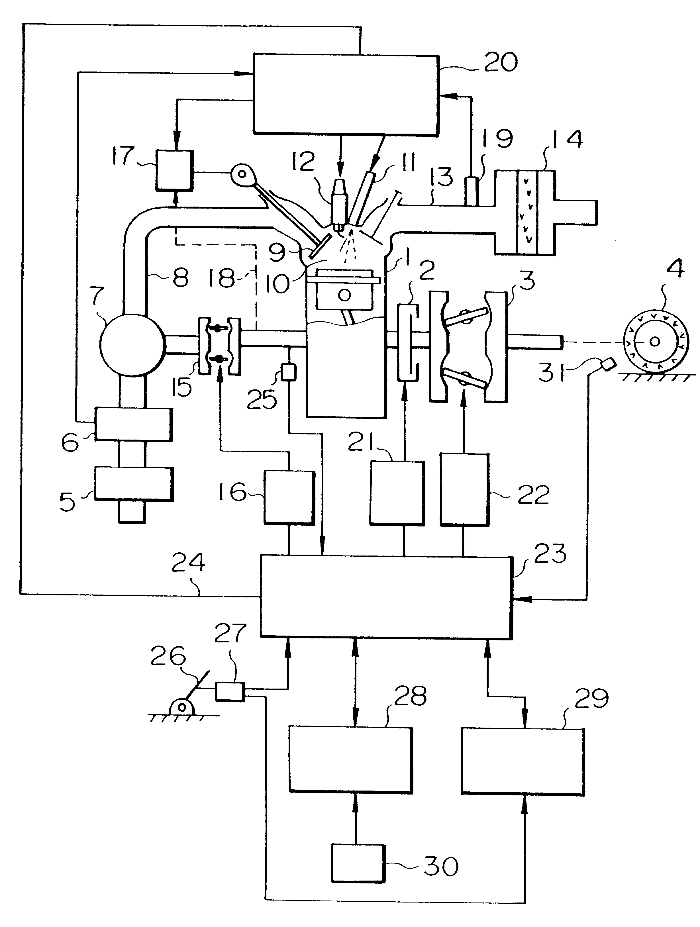
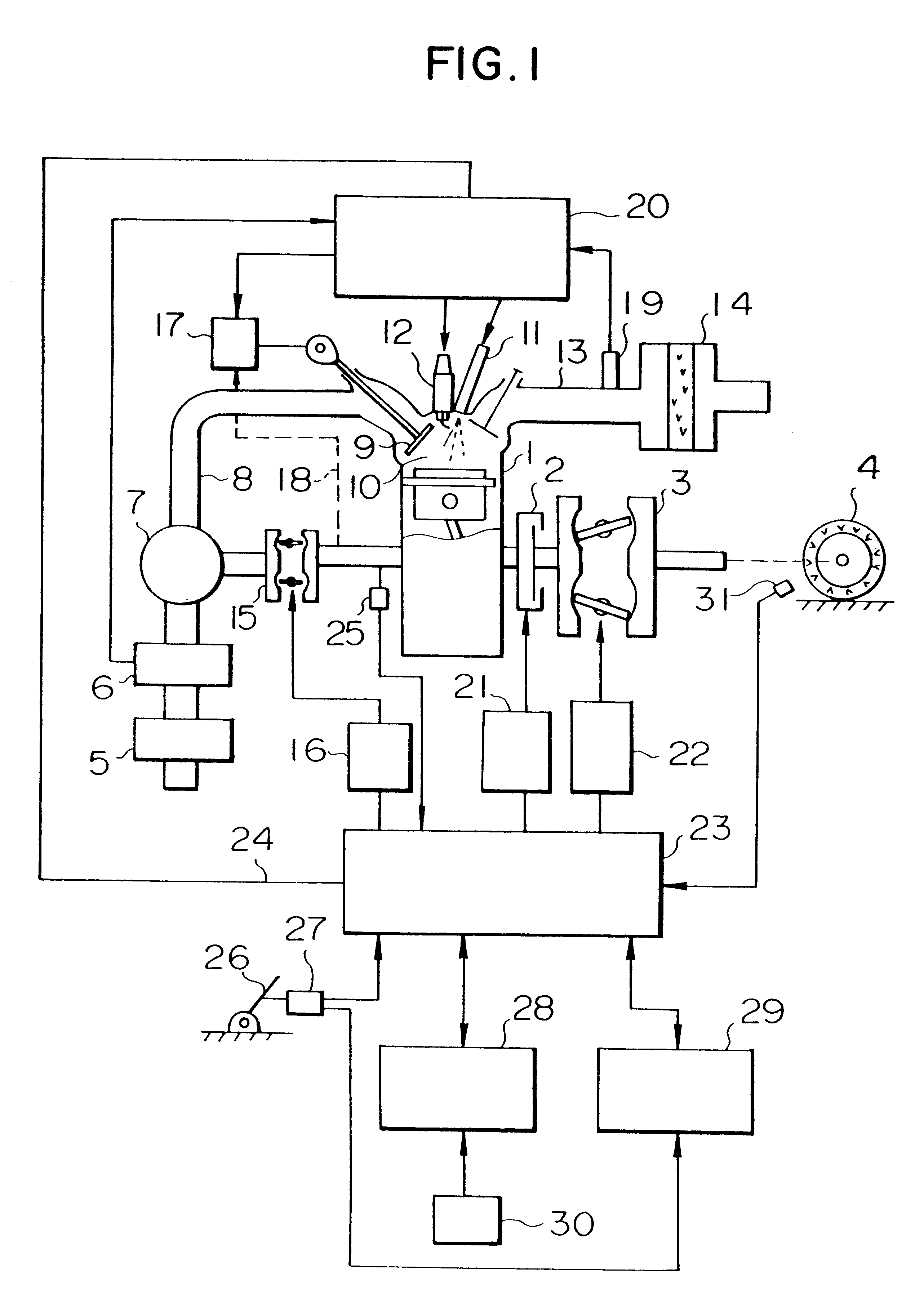
Explanation will be made hereinbelow an engine which is used in the above-mentioned drive system. Referring to FIG. 17, the engine 201 incorporates a piston 202 having a concave combustion chamber, an intake valve 203, an exhaust valve 204, a fuel injection valve 205, a spark plug 206, an intake pipe 207 in which an air cleaner 208 is located, and an exhaust pipe 209 in which a catalytic converter 210 for purifying nitrogen oxide is incorporated. The intake valve 203 is driven by a low load cam 211 and a high load cam 212. The exhaust valve 204 is driven by a cam 213. The cam 211 presses a rocker arm 214 while the cam 212 presses a rocker arm 215. In this arrangement, under a low load, a solenoid 216 is energized so as to connect the rocker arm 215 with the intake valve 203. The spark plug 206, the fuel injection valve 205 and solenoids 216, 217 are operated under the control of a control apparatus 218, a position (degree of depression) of an accelerator pedal 219 detected by a pote...

second embodiment

Explanation will be hereinbelow made of an engine used in the drive system according to the present invention.

Referring to FIG. 31 which shows an arrangement of an engine and components therearond in the second embodiment, the engine in this embodiment is a gasoline type four cylinder MiIller cycle engine 310 having a cylinder head formed therein with an intake port 313 and an exhaust port 314 which are connected respectively to an intake pipe 320 and an exhaust pipe 330. Further, a fuel injection valve 380 and a spark plug 340 are provided in the cylinder head. Further, an intake valve 315 is provided in the intake port 313, and an exhaust valve 316 is provided in the exhaust port 316. The intake pipe 310 is provided therein with a throttle valve 321 for adjusting the flow rate of air flowing therethrough. Meanwhile, the exhaust pipe 330 is provided therein with a catalytic converter 331 for removing detrimental components from exhaust gas flowing therethrough. A water jacket 318 r...


PUM


Abstract

A drive system composed of an engine and a transmission is controlled in accordance with a desired wheel toque corresponding to a position of an accelerator, and a present vehicle speed in such a way that a speed ratio of the transmission is determined in consideration with torque factors such as an air-fuel ratio on the engine side, thereby it possible to optimize the control in order to reduce the emission of exhaust substance such as NOx and to enhance the acceleration performance and the fuel economy.

Description

BACKGROUND OF THE INVENTIONThe present invention relates to a control apparatus for a drive system composed of an engine and a transmission, and in particular to a control apparatus for a drive system composed of an engine such as a gasoline engine or a Diesel-engine and a transmission such as an automatic transmission in combination of a torque converter and a gear train, or a belt-and-pulley type continuous variable transmission.RELATED ARTFor example, Japanese Patent Publication No. 63-45977 and Japanese Patent Publication No. 63-45976 disclose therein a control apparatus which sets a desired wheel torque (which corresponds to a torque that can obtained at the final speed-change gear such as differential gear or a speed ratio between the engine speed and the wheel speed since the engine torque is substantially constant, irrespective of an engine speed, over an operating speed range) in accordance with an opening degree of the throttle valve of an engine which is manipulated by a ...

Claims


Application Information

Patent Timeline
IPC IPC(8): F02M61/16F02M61/06F02D41/04F02M61/00F02M61/18F02M59/10F02D41/00F02M59/00F02D13/02F02D41/34F01L13/00F02B39/02F02B39/12F02M45/08F02M41/08F02M41/12F02M45/00F02M51/06F02M47/02F02B75/00F02M63/00F02B23/10F02B3/06F02B75/12F02B3/00
CPCF01L13/0036F02B39/12F02D13/0207F02D13/0215F02D13/0223F02D13/0234F02D13/0269F02D41/0002F02D41/04F02D41/34F02M41/123F02M45/08F02M47/02F02M47/027F02M51/0671F02M59/102F02M61/06F02M61/161F02M61/18Y10T477/67F02B3/06F02B23/101F02B2075/125F02B2275/32F02D2013/0292F02D2041/001F02D2041/389F02D2200/501F02M2200/21Y02T10/44Y02T10/142Y02T10/42Y02T10/123F01L2201/00Y02T10/12Y02T10/40B60K17/00
Inventor OHYAMA, YOSHISHIGEFUJIEDA, MAMORUNOGI, TOSHIHARUSHIRAISHI, TAKUYAOHSUGA, MINORU
Owner HITACHI LTD
Why Eureka
Try Eureka