
Process for preparing cycloalkanone

a technology of cycloalkanone and process, applied in the field of cycloalkanone, can solve the problems of low production rate of cyclohexanone, process requires the use of expensive exhaust gas treatment facilities, and the inability to obtain cyclohexanone with high efficiency

Inactive Publication Date: 2003-03-04
DAICEL CHEM IND LTD
View PDF8 Cites 21 Cited by
  • Summary
  • Abstract
  • Description
  • Claims
  • Application Information

AI Technical Summary

Benefits of technology

Another object of the present invention is to provide a process capable of efficiently producing cycloalkanones through a sequence steps without subjecting a by-produced cycloalkanol to a dehydrogenating step.
Still another object of the present invention is to provide a process capable of producing, under mild or moderate conditions, cycloalkanonesat high conversions and selectivities without requiring the treatment of exhaust gas.
The inventors of the present invention made intensive and extensive studies to achieve the above objects, and finally found that a cycloalkanone can be efficiently formed by oxidizing a cycloalkane in the presence of a specific oxidizing catalyst (oxidation catalyst) through a series of steps. The present invention was accomplished based on the above findings.

Problems solved by technology

However, a conventional process not only involves the generation of a large amount of by-products but also pose a problem of low production rate of cyclohexanone, and further requires the by-produced cyclohexanol be treated by dehydrogenation.
Moreover, when nitric acid or the like is employed for the oxidation of a cycloalkane, the process requires the use of an expensive exhaust gas-treatment facilities.
Therefore, despite the process being complicated, a cyclohexanone cannot be obtained with high efficiency.

Method used


Image

  • Process for preparing cycloalkanone
  • Process for preparing cycloalkanone
  • Process for preparing cycloalkanone

Examples


example 1

(1) Catalytic Solution-preparing Step

A catalytic solution was prepared in proportions of cyclohexane 10,000 g / H, N-hydroxyphthalimide 10 g / H, and cotaltacetonato 64 g / H.

(2) Oxidation Step

The catalytic solution prepared in the above proportion, cyclohexane, and air were fed to a reactor 2 at rates of supply of 840 g / H and 1.3 Nm.sup.3 / H, respectively, and the mixture was reacted at 160.degree. C. and 40 atm for a residence time of two hours. At a conversion of 11%, the cyclohexane was converted into a cyclohexanone and a cyclohexanol at selectivities of 40% and 49%, respectively.

(3) Catalyst-separating Step

The crude reaction mixture was cooled to 20.degree. C., and the catalyst was separated by filtration at a rate of 9.8 g / H. The separated catalyst was treated by incineration to recover the cobalt contained therein and then recycled to the reaction system for reuse. In an extraction column 4 equipped with rings and plates, the filtrate was subjected to an extraction step with water...

example 2

(1) Catalysti Solution-preparing Step

A catalytic solution was prepared in proportions of cyclohexanone 1,000 g / H, N-hydroxyphthalimide 160 g / H, and cobalt acetonato 64 g / H.

(2) Oxidation Step

The catalytic solution prepared in the above proportion, cyclohexane, and air were fed to a reactor 22 at rates of supply of 840 g / H and 1.3 Nm.sup.3 / H, respectively, and the mixture was reacted at 160.degree. C. and 40 atm for a residence time of four hours. At a conversion of 32%, cyclohexane was converted into a cyclohexanone and a cyclohexanol at selectivities of 89% and 5%, respectively.

(3) Catalyst-separating Step

The crude reaction mixture was cooled to 20.degree. C., and the catalyst was separated by filtration at a rate of 158 g / H. In an extraction column 24 equipped with rings & plates, the filtrate was subjected to an extraction step with water at 20.degree. C. to extract an acid having a higher-boiling point and the like.

(4) Lower-boiling Point Component-separating Step

In a perforated...

example 3

(1) Catalytic Solution-preparing Step

A catalytic solution was prepared in proportions of acetic acid 1,000 g / H. N-hydroxyphthalimide 160 g / H, and cotalt acetonato 64 g / H.

(2) Oxidation Step

The catalytic solution prepared in the above proportion, cyclohexane, and air were fed to a reactor 32 at rates of supply of 840 g / H and 1.3 Nm.sup.3 / H, respectively, and the mixture was reacted at 75.degree. C. and 40 atm for a residence time of 4 hours. At a conversion of 31%, the cyclohexane was converted into a cyclohexanone and a cyclohexanol at selectivities of 90% and 5%, respectively.

(3) Lower-boiling Point Component Separating Step

In a forced circulation-type evaporator, the crude reaction mixture was separated into the lower-boiling point component comprised of cyclohexane, water and others, and the higher-boiling point component comprised of acetic acid, the KA oil, the catalyst and others. Using a perforated-plate column with 30 plates, water and the cyclohexane were separated from the...


PUM

PropertyMeasurementUnit
Substance countaaaaaaaaaa

Abstract

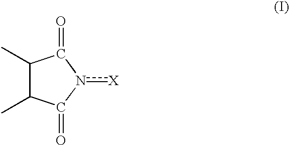
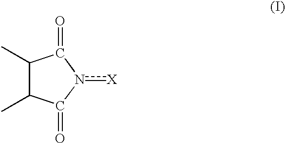
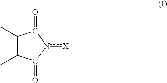
A series of steps of (A) a step for bringing a cycloalkane into contact with molecular oxygen (oxidizing reactor 2) in the presence of an oxidizing catalyst having an imide unit of the following formula (I):wherein X represents oxygen atom or hydroxyl group;(B) a step for separating the catalyst, and by-produced acid component or a derivative thereof from the reaction mixture (filter 3, extracting column 4, hydrolyzing unit 7, saponifying unit 8); and(C) steps for separating the cycloalkane, a cycloalkanol, and a cycloalkanone from the reaction mixture individually (distilling columns 5, 6, 9, and 10) makes it possible to produce cycloalkanones efficiently. A first component (lower-boiling point component) containing the cycloalkane and a second component (higher-boiling point component) containing the cycloalkanone and cycloalkanol may be separated from the reaction mixture, and the cycloalkanone and the cycloalkanol may be separated from the higher-boiling point component. Such production process is capable of providing cycloalkanones with high efficiency.

Description

The present invention relates to a process for producing a cycloalkanone from a cycloalkane using molecular oxygen in the presence of a particular oxidizing catalyst.BACKGROUND TECHNOLOGYAmong cycloalkanones, cyclohexanone is a compound useful in producing .epsilon.-aminocaprolactam which is a raw material for nylon. It is known that, in the production of cyclohexanone, in the liquid phase, cyclohexane is oxidized with molecular oxygen or a molecular oxygen-containing gas in the presence of a soluble cobalt salt as a catalyst (e.g., cobalt 0.1 to 100 ppm) to form cyclohexanone and cyclohexanol, followed by the conversion of the by-produced cyclohexanol into a cyclohexanone by subjecting the cyclohexanol to a dehydrogenating reaction using a dehydrogenator ("Handbook of Chemistry: Applied Chemistry" page 536, Oct. 15, 1986 version, edit by Nippon Kagaku-kai, published by Maruzen).However, a conventional process not only involves the generation of a large amount of by-products but als...

Claims


Application Information

Patent Timeline
IPC IPC(8): B01J31/02C07C29/00C07C29/50C07C45/00C07C45/82C07C45/33B01J31/22B01J31/40C07B61/00C07C49/403
CPCB01J31/006B01J31/0247B01J31/40C07C29/50C07C45/33C07C45/82C07C35/08C07C49/403B01J2231/70C07C2101/14Y02P20/584C07C2601/14
Inventor MIURA, HIROYUKIWATANABE, HITOSHIINA, TOMOHIDENAKAJIMA, HIDEHIKO
Owner DAICEL CHEM IND LTD
Learn More