Projection exposure device

a technology of projection and exposure device, which is applied in the direction of instruments, printers, therapy, etc., can solve the problems of time drift of properties and distribution of illumination intensity in the pupil plan

Inactive Publication Date: 2003-03-18
CARL ZEISS SMT GMBH +1
View PDF6 Cites 103 Cited by
  • Summary
  • Abstract
  • Description
  • Claims
  • Application Information

AI Technical Summary

Problems solved by technology

Such changes of the illumination intensity distribution in the pupil plane can for example result from

Method used


Image

  • Projection exposure device
  • Projection exposure device
  • Projection exposure device

Examples


Embodiment Construction

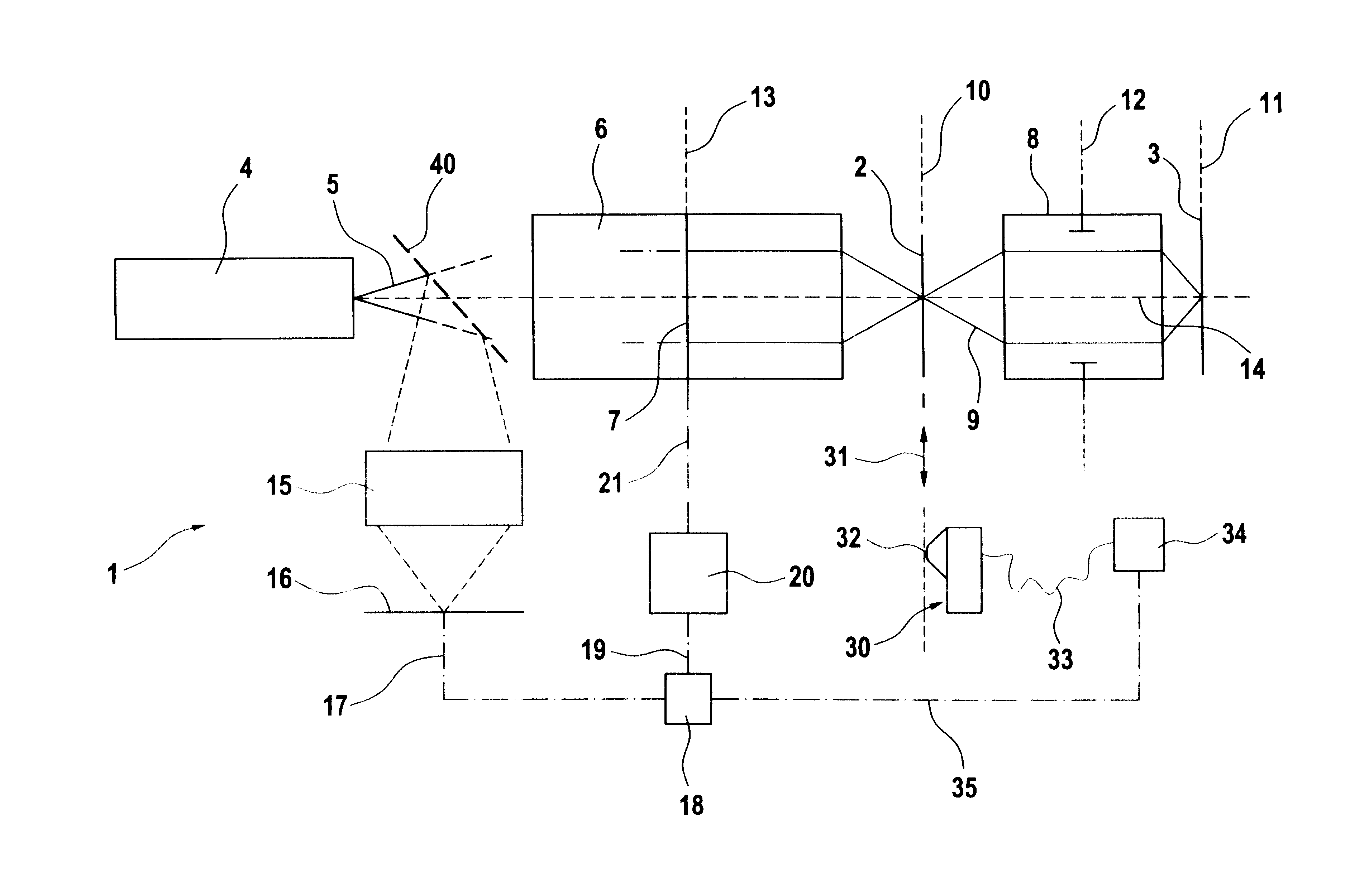
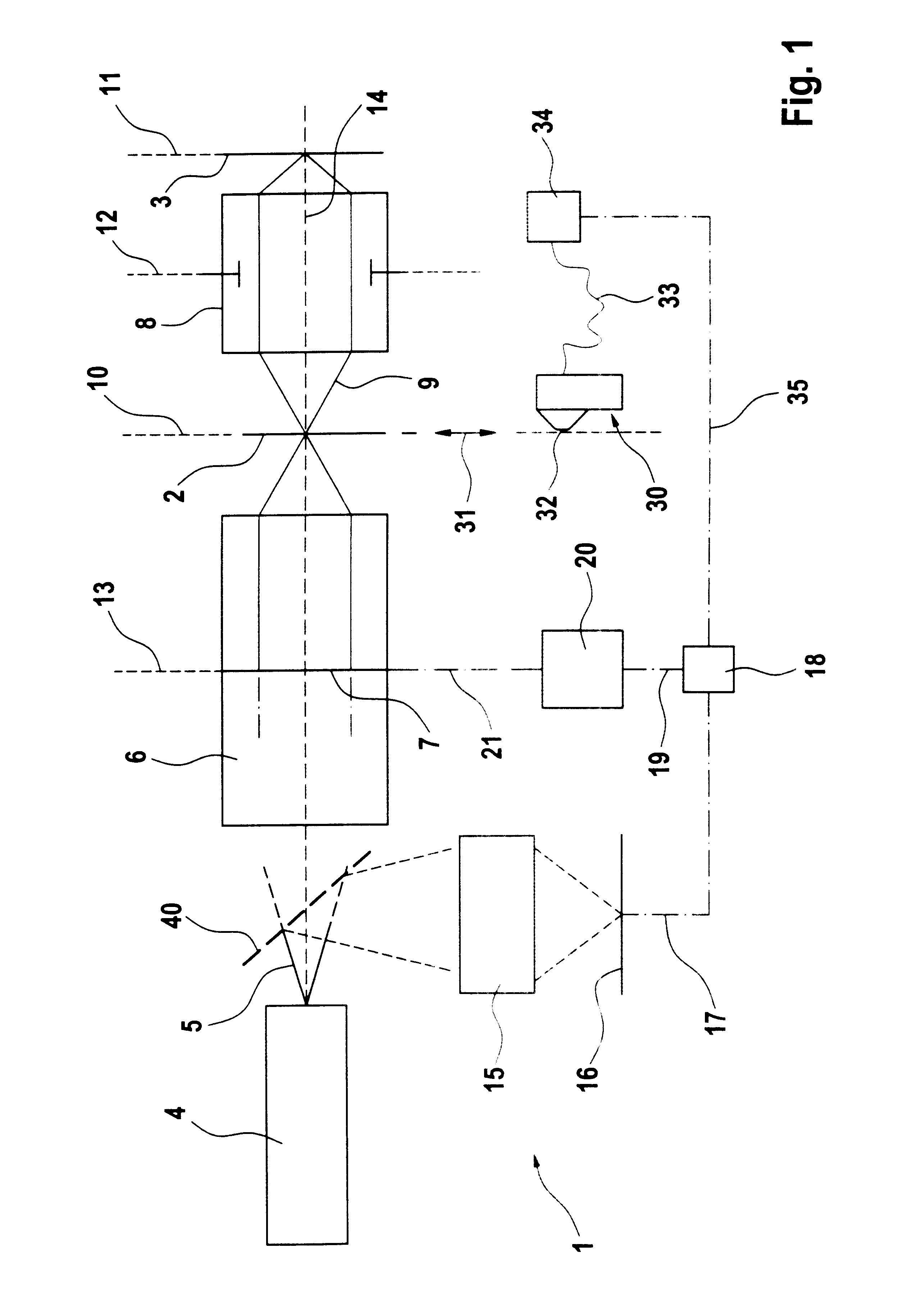
In FIG. 1 a complete projection exposure device shown with the reference 1 for micro-lithography is illustrated. Using this a structure on a recticle 2 can be transferred onto the surface of a wafer 3.

A UV laser 4, for example an ArF excimer laser with a wavelength of 193.3 nm serves as the light source for the projection exposure device 1. A projection light bundle 5 emitted by the UV laser 4 first enters illumination optics 6. The ray path of the projection light bundle 5 is only indicated for the sake of clarity between the UV laser 4 and the illumination optics 6. The illumination optics 6 is for the most part shown diagrammatically in FIG. 1 as a block and can have a series of optical sub-assemblies, for example a zoom-lens, diffractive optical elements and a glass rod to homogenise the projection light bundle 5.

In its journey through the illumination optics 6 the projection light bundle 5 passes a pupil filter 7 positioned in a pupil plane 13, which is still to be described in...


PUM


Abstract

A projection exposure device, in particular for micro-lithography, serves to produce an image of an object in an image plane positioned in an object plane. This happens with the aid of a light source emitting projection light and illumination optics positioned in the ray path between the light source and the object plane. In addition projection optics positioned in the ray path between the object plane and the image plane serve to guide the projection light. A filter (7) is positioned in a filter plane which lies in the vicinity of a pupil plane between the light source and the object plane. This has a moveable filter element (22') which has at least in certain areas (24) for the projection light a transmission factor which is greater than zero and less than 100%. The moveable filter element (22') is moveable in the filter plane and has a distribution of the transmission factor over the filter face, in such a way that the intensity distribution of the projection light perpendicular to the optical axis (14) in the ray path after the filter (7) changes with the movement of the filter element (22'). With such a filter (7) an illumination angle distribution can be adapted to a pre-set value (FIG. 5).

Description

The invention relates to a projection exposure device, in particular for micro-lithography, to produce an image of an object in an image plane positioned in an object plane with a radiation source emitting projection radiation, with illumination optics positioned in the ray path between the light source and the object plane and projection optics positioned in the ray path between the object plane and the image plane, whereby a filter with a moveable filter element is placed in a filter plane, which lies in the vicinity of a pupil plane between the light source and the object plane, which is moveable in the filter plane and has a distribution of the transmission factor over the filter face in such a way that the intensity distribution of the projection light perpendicular to the optical axis in the ray path after the filter, changes with the movement of the filter element.BACKGROUND TO THE INVENTIONSuch a projection exposure device is known from U.S. Pat. No. 5,264,898. The filter us...

Claims


Application Information

Patent Timeline
IPC IPC(8): G03F7/20G02B5/22H01L21/027G02B5/00
CPCG03F7/70075G03F7/70191G03F7/701
Inventor ANTONI, MARTIN
Owner CARL ZEISS SMT GMBH
Why Eureka
Try Eureka