Identifier system and components for optical assemblies

a technology of optical assemblies and identification systems, applied in the direction of optical elements, cladded optical fibres, instruments, etc., can solve the problems of difficult to discern differences between components, and not uniformly perpendicular to the direction of optical components, and many of the individual components of optical assemblies are typically small and technically complex,

Inactive Publication Date: 2003-04-01
CIRREX
View PDF7 Cites 59 Cited by
  • Summary
  • Abstract
  • Description
  • Claims
  • Application Information

AI Technical Summary

Problems solved by technology

Numerous difficulties exist in the manufacturing of quality optical assemblies, because many of the individual components of optical assemblies are typically small and technically complex.
For example, the relatively small size of each component makes differences between the components, or even differences within individual components, difficult to discern.
Because the end face is angled, it is not uniformly perpendicular to its axis or the axis of the optical component to which it is to be coupled.
Conventional optical testing is time consuming when performed in a manufacturing environment.
Additionally, after the two components are coupled together, another testing interruption is necessary for quality control of the assembled components.
Furthermore, optical testing performed in a manufacturing environment is not as accurate as optical testing performed in a testing environment.
The inaccuracy of that testing can cause improper alignment between the components, which provides a lower quality assembly.

Method used


Image

  • Identifier system and components for optical assemblies
  • Identifier system and components for optical assemblies
  • Identifier system and components for optical assemblies

Examples


Embodiment Construction

The present invention will be described in detail with reference to the accompanying drawings, in which like reference numerals represent like elements.

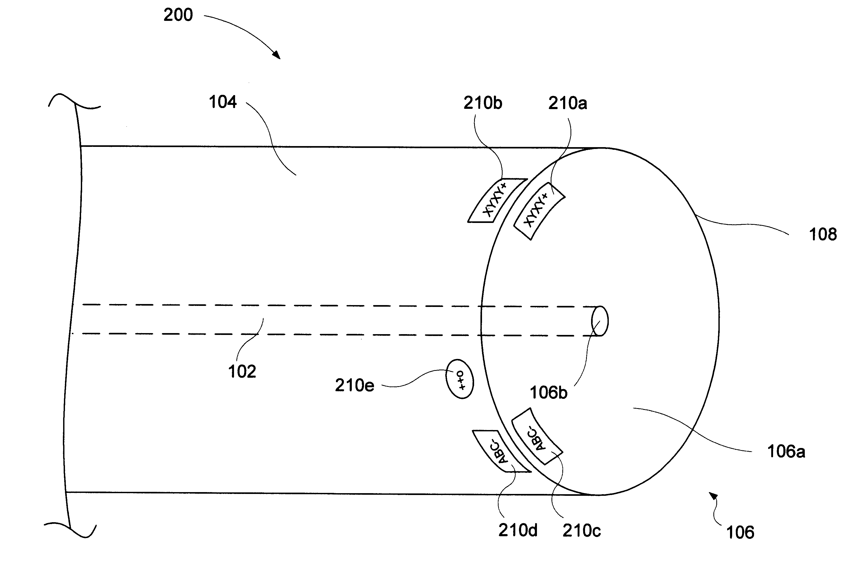
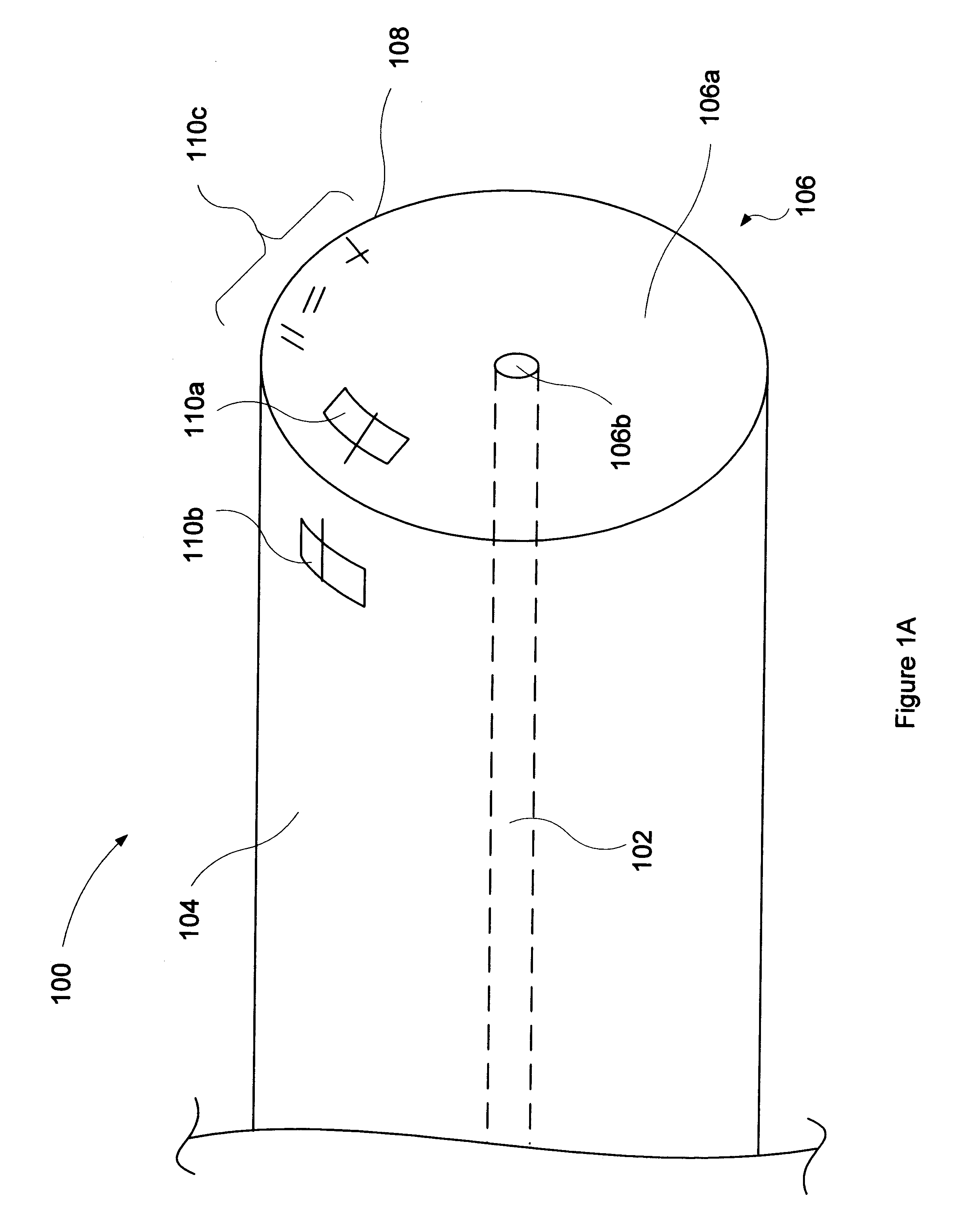
As used herein, the term "waveguide" refers to an optical structure having the ability to propagate light in a bounded propagation mode along a path parallel to its axis and to contain the energy within or adjacent to its surface. Typically, such waveguides can propagate light in the 700-2000 nanometer (nm) range.

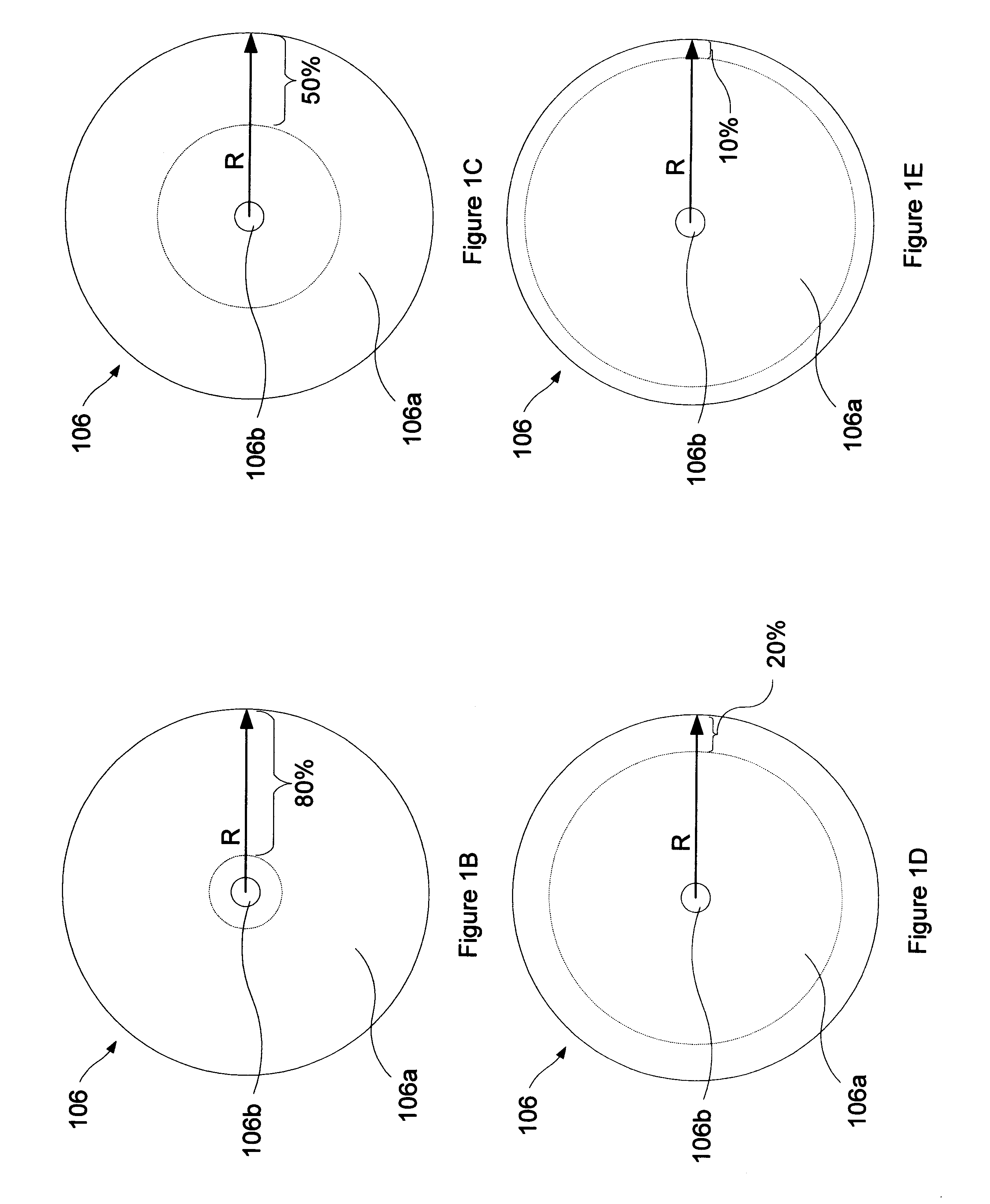
The present invention facilitates the automation of manufacturing quality optical assemblies having waveguides as a component. In the present invention, an identifying mechanism is provided on or in a high-performance waveguide. The identifying mechanism is machine-readable. For example, the identifying mechanism may be read by an optical method such as using a laser interference pattern. Machine reading allows a quick and accurate determination of the information included within the identifying mechanism, thereby allowing p...


PUM

PropertyMeasurementUnit
areaaaaaaaaaaa
indices of refractionaaaaaaaaaa
sizeaaaaaaaaaa

Abstract

A device and system for eliminating repeated testing of optical components while manufacturing an optical assembly can include a high-performance optical component having a machine-readable identifier disposed within the peripheral area of its end face. The machine-readable identifier can be etched into the end face and can provide information about the component, such as any one of the following optical characteristics: orientation, manufacturing information, and dimensions and compositions of the materials of the optical component. The optical component can also have a plurality of machine-readable identifiers disposed within the peripheral area of its end face, where each can provide different information. Optical components can then be automatically and precisely aligned before being mated to form an optical assembly. A determination of the optical characteristics, information, and alignment of the components can be possible even after the components are mated together.

Description

1. Field of the InventionThe present invention relates to the automated production of quality optical assemblies. More particularly, the present invention relates to high-performance waveguides having a machine-readable identifier and automated production systems using the same.2. Description of the Related ArtIn recent years, optical assemblies have been recognized as offering a high potential for solving problems in a number of commercial applications. Such optical assemblies include optical waveguides, planar light guide circuits (PLCs), waveguides for distributed feedback lasers, and other like assemblies. High quality optical assemblies are particularly useful in, for example, telecommunications, medical diagnostics, pharmaceutical research, and chemical process monitoring. Additionally, ultra high-performance optical waveguides, such as waveguides associated with high-performance filters and precision micro optics, have the potential to fill a critical role in the continuing d...

Claims


Application Information

Patent Timeline
Patent Type & Authority Patents(United States)
IPC IPC(8): G01N21/47G01N21/77G01N21/65G01N21/63G02B6/24G02B6/34G02B6/04G02B6/26
CPCG02B6/02G02B6/29368G02B6/241G02B6/262G02B6/04G02B6/02052
Inventor HOLTER, DWIGHT J.WACH, MICHAEL L.
Owner CIRREX
Why Eureka
Try Eureka