The present invention relates to a probe for touch sensing to determine the position of a workpiece in a robotic welding
system and an improved system using the novel probe. In accordance with the invention, a rigid, elongated feeler with a touch tip is mounted in a mechanism adjacent the welding gun of the robotic welding system so that the contact point of the touch tip can be extended by instructions from the
computer program to a fixed distance beyond the end of the welding gun. In this fixed extended position, the feeler is moved by a
computer program to touch the workpiece at many locations. In practice, six to eight touches are used to determine the exact position of the workpiece preparatory to the welding operation. The feeler is fixed with respect to the welding gun so that the determined orientation calculated by the computer will determine the exact spatial location of the welding path to be processed by the computer movement of the welding gun. The invention does not present the problems associated with using the extended welding wire as the feeler moved into several locations for the purposes of generating a
computer analysis of the
exact location of the workpiece. When using the wire for the purposes of touch sensing, the wire can only be moved downward by the movement of the welding gun at a rate of about 15 millimeters per second. By using the present invention, the probe can be moved by the
robotic arm at a rate of approximately 200 millimeters per second. Consequently, the six to eight steps used in a touch sensing program are performed using the present invention in about eight minutes. The same process using the extended welding wire requires over twenty minutes and causes bending of the wire causing less accurate location. Indeed, the wire must be held in the gun, clipped and extended a fixed distance before the wire is useable for the touch sensing program. The present invention allows the fixed feeler to be used rapidly without concern for
distortion during the
processing. When seven touches are necessary for locating a weld position, the use of the fixed feeler of the present invention is extremely advantageous by saving time and resulting in better accuracy.
The invention involves the novel probe and also the concept of retracting the probe after the touch sequence has been processed by the computer program used for the robotic welding of the workpiece. The probe is parallel to the wire and is moved into the extended operative position. Thereafter, it is retracted into an inoperative position where it is not capable of interference with movement of the welding gun during welding. The wire extending from the welding gun is not used for the location of the workpiece. Thus all of the disadvantages previously associated with such procedure are avoided. Although it is preferable that the feeler or probe be parallel to the welding gun the probe may be at a
fixed angle to the welding gun. This position of the probe or feeler introduces complexity in the
computer programming and also cause a certain amount of inaccuracy in the touch sensing process. By using the invention, there is no need to provide a
brake in the gun to hold the welding wire in a
fixed position for touch sensing. Furthermore, it is not necessary to contact the workpiece at an angle although this can be done if the computer program requires such orientation of the probe constructed in accordance with the present invention.
The retractable touch sensing probe is used on an
arc welding robot to aid in the sensing of workpiece orientation. It is rigid and retractable so that there is no deformation of the sensing device. The
cycle time is substantially reduced and the probe retracts, allowing unrestricted weld
torch or gun movement along the weld path. In the practical implementation of the present invention, the probe consists of a
pneumatic cylinder using a two way pneumatic
solenoid valve to shift the rigid feeler into the extended touch position or the retracted operative position. A standard output
bus merely activates the
solenoid valve to move the probe outward into the operative position. The electromechanical device for operating the
solenoid valve, in one embodiment also functions to close a switch that applies a
voltage to the probe. This
voltage is then measured by the computer or
electric arc welder for indication of a touch to the workpiece by a
detector. When the
voltage level plunges, contact of the feeler or probe with the workpiece is detected. By using standard robot touch sensing
software, the novel probe is linked to the touch sense I / O outlet to determine when the probe is extended for the
processing inputting data calculated by the
software program. The same digital output that extends the probe also connects the probe to a positive output voltage. This creates an open circuit with the touch sensing voltage being the voltage between the probe and the workpiece. When the robot touches the workpiece, the voltage potential between the two points drops. This is detected by either the
robot controller or the
welding power supply if equipped with a standard touch sensing capability. After the various touches have been recorded to calculate the position of the workpiece, the probe retracts so it no longer extends past the
torch body of the gun, thereby allowing the
welding process to proceed uninhibited.
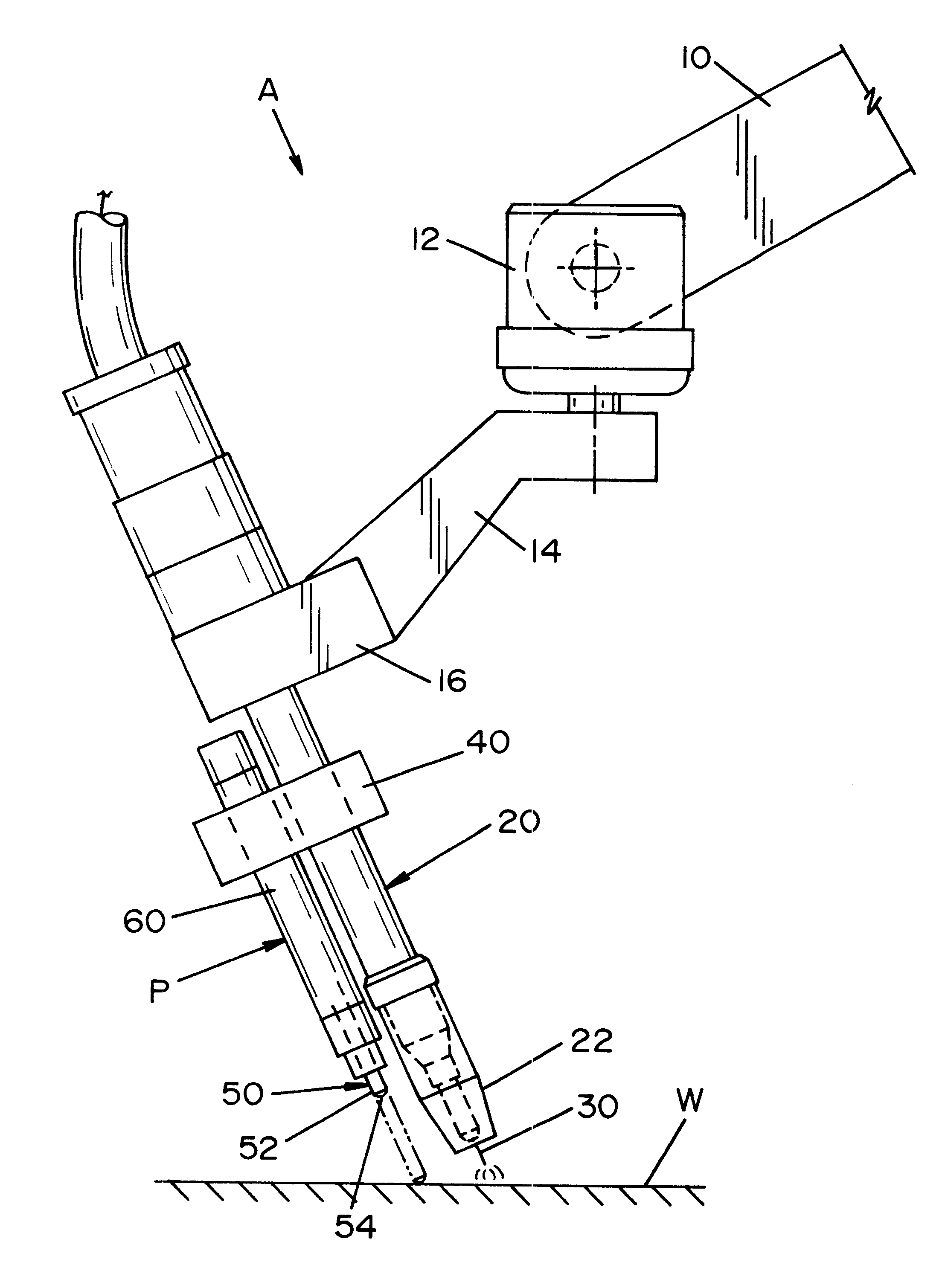
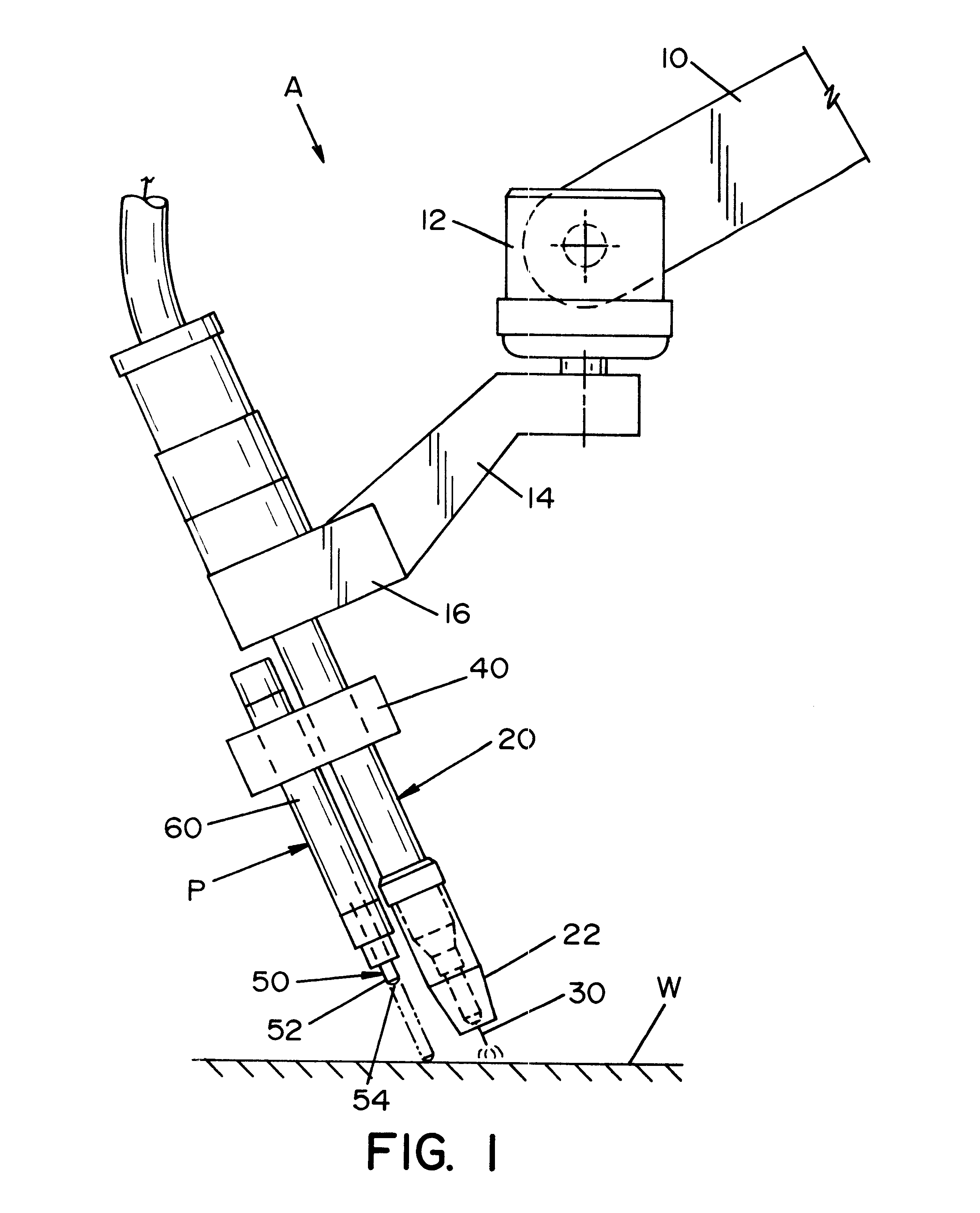
In accordance with another aspect of the present invention, the feeler extends parallel to the extended direction of a gun or
torch body. Thus, when the feeler is extended, it is moved by the robot during the touching sequence just as the torch would be moved, but with a certain offset. In practice, the moving mechanism is a cylinder mounted on the gun and the feeler is carried by a
piston movable in the cylinder when the feeler moves between the two positions. A lower chamber in the cylinder and below the
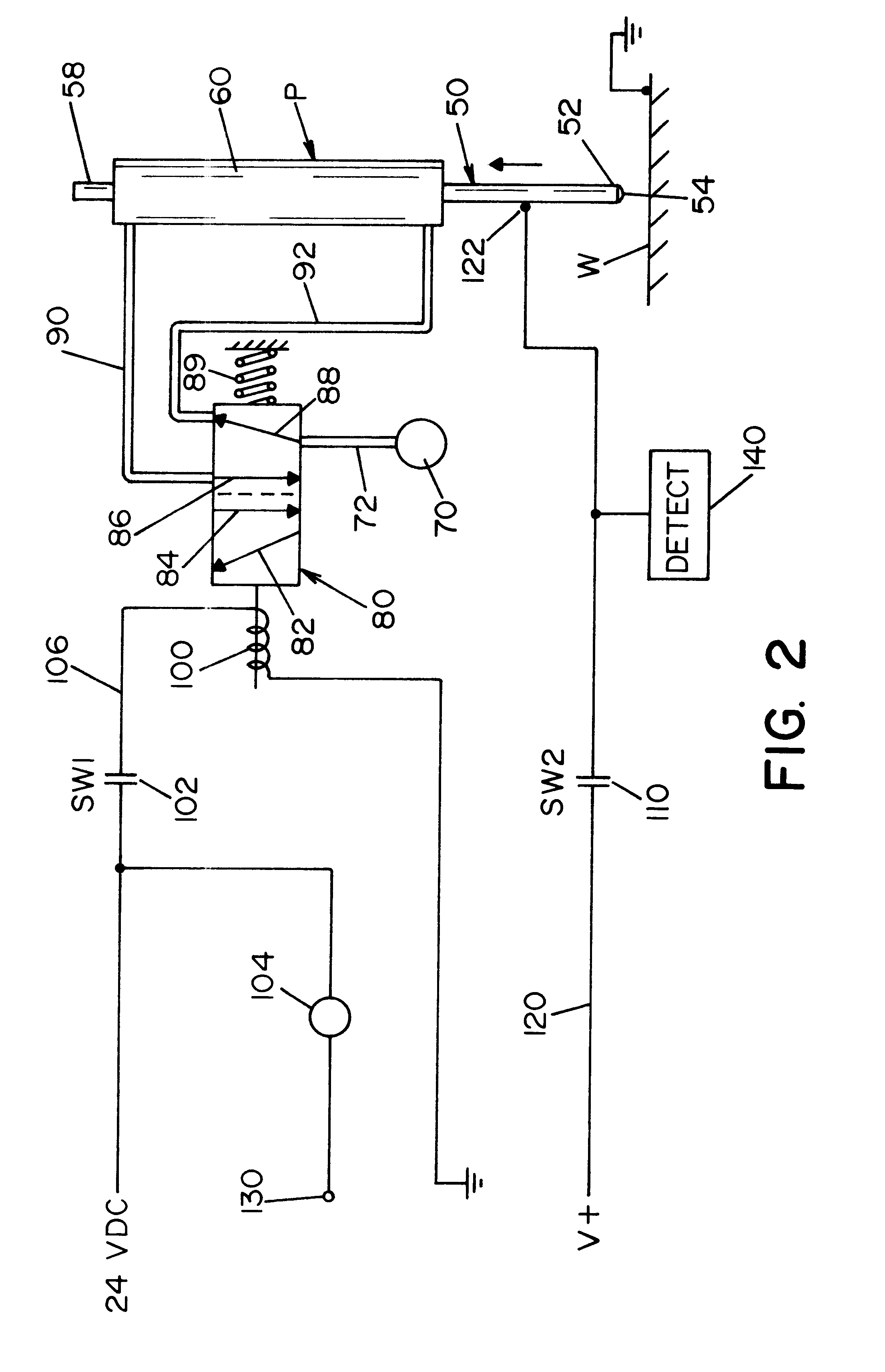
piston receives pressurized fluid from a electromechanical operated valve to introduce the fluid into the lower chamber. This moves the feeler from the extended position to the retracted position. It is possible to force the probe in the extended position by use of a spring with the
fluid pressure moving the feeler against the spring to retract the feeler. In a like manner, a chamber above the
piston is used in practice to shift the feeler into the extended position. When this occurs, the feeler moves against the stop in the cylinder to set the outermost contact point of the feeler. The valve for directing fluid either to the upper chamber or the lower chamber is operated by electromechanical device, such as a solenoid operated by a
relay. In practice, one switch is closed by the electromechanical device to connect the voltage to the feeler. Another switch is closed to shift the valve between the retract position and the extended position. In practice, the switches are operated optically to prevent
noise.
Yet another object of the present invention is the provision of a probe, as defined above, which probe is rigid and elongated and overcomes the disadvantages of using a flexible welding wire as the feeler for a touch sensing sequence in a computer controlled robot system.

