Solar cell arrangements

a solar cell and arrangement technology, applied in the direction of secondary cell servicing/maintenance, electrochemical generators, transportation and packaging, etc., can solve the problems of loss of active solar cell area, current being driven in reverse, and cell may irreversibly break down

Inactive Publication Date: 2003-05-13
E2V TECH (UK) LTD
View PDF7 Cites 52 Cited by
  • Summary
  • Abstract
  • Description
  • Claims
  • Application Information

AI Technical Summary

Problems solved by technology

This may lead to current being driven in reverse through the shadowed solar cell.
If the power density is sufficiently high, the cell may irreversibly break down.
This may lead to a loss of active solar cell area.
For example, where a solar cell is manufactured from a circular wafer forming the substrate on which the p-n junction is fabricated, the cell dimensions are sometimes sufficiently large in comparison that a regular, rectangular solar cell cannot be derived from the wafer without two of the corners being lost.
This is more difficult to cut in practice, however, and is thus not preferred.
GaAs cells are particularly vulnerable, tending to break down at lower reversible voltages than silicon solar cells, for example.

Method used


Image

  • Solar cell arrangements
  • Solar cell arrangements
  • Solar cell arrangements

Examples


Embodiment Construction

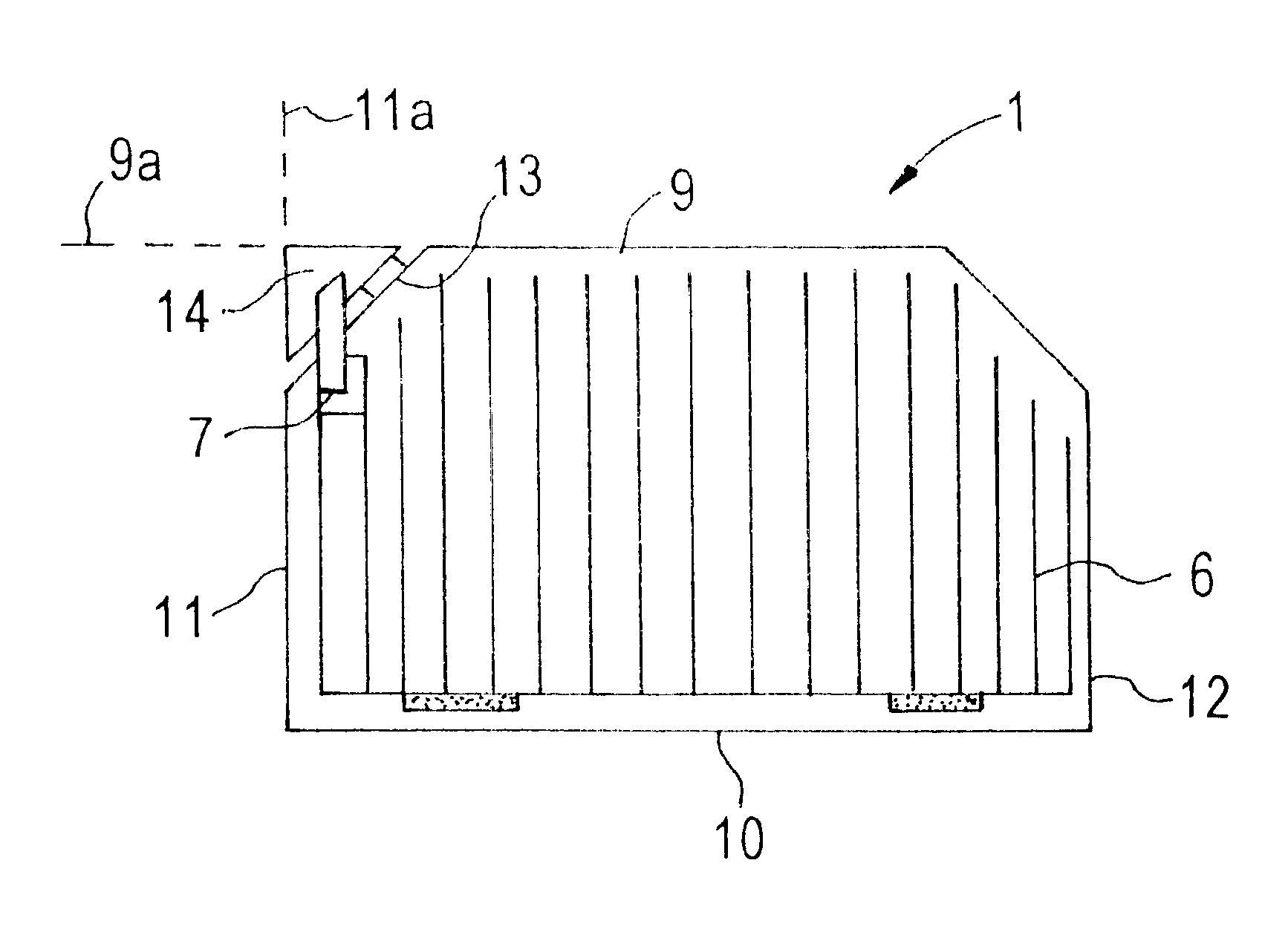
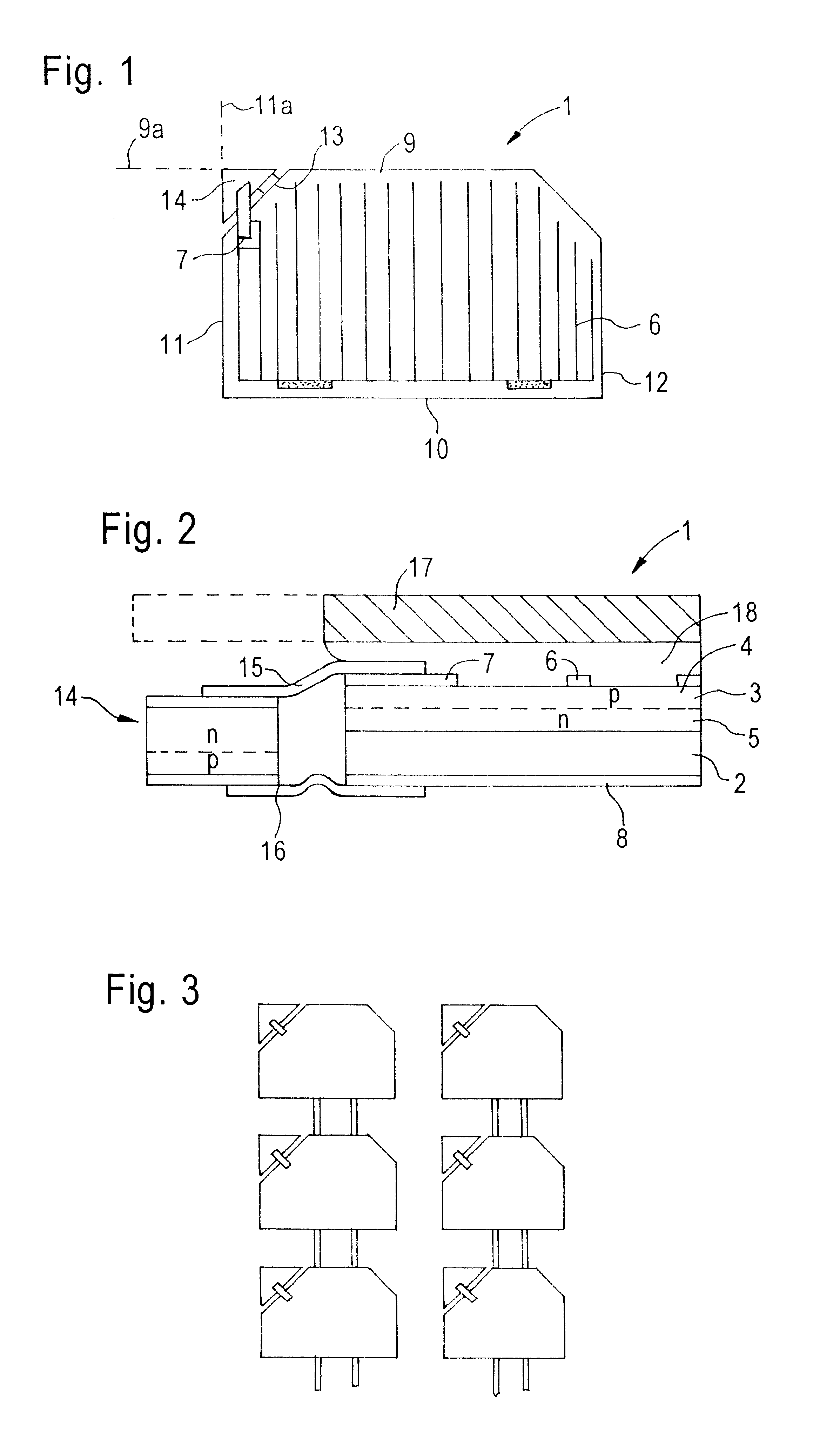
With reference to FIGS. 1 and 2, a solar cell 1 comprises a germanium substrate 2 on which is grown an expitaxial GaAs layer 3 doped to give p and n type layers 4 and 5 with a junction between them. A front metal contact grid 6 located on the GaAs layer 3 includes a supplementary pad 7. There is a rear metal layer 8 on the rear surface of the germanium substrate 2.

In plan view, the solar cell 1 is generally rectangular having a parallel sides 9 and 10, and sides 11 and 12 with two of the corners of the rectangle being cropped. At one of the cropped corners, a third oblique side 13 exists between the mutually orthogonal sides 9 and 11. In the region bounded by projections 9a of side 9 and 11a of side 11 and the oblique side 13, a silicon protection diode 14 is located. In this embodiment, the protection diode 14 is of triangular section in plan view. The diode 14 is electrically connected across the cell 1 by a front interconnect 15 to the supplementary pad 7 and by a back interconne...


PUM


Abstract

In a solar cell arrangement, a generally rectangular solar cell has mutually orthogonal sides in plan view and a third oblique side to them which adjoins them. A protection diode is located in the region bounded by the third side and projections of the first and second sides. The protection diode is electrically connected to the solar cell. Use of the invention enables protection to be provided individual solar cells of a solar cell array without a significant loss in the area occupied by the light sensitive solar cell surfaces.

Description

This invention relates to solar cell arrangements and more particularly to the protection of solar cells against reverse current through them.BACKGROUND TO THE INVENTIONIn one type of solar cell (or photovoltaic cell), a voltage is developed across a p-n junction in a semiconductor when it is irradiated by photons. A plurality of solar cells may be connected together in an array to provide a power supply, such arrangements commonly being used in spacecraft and satellites for example. During operation, there may be circumstances where a single solar cell is shadowed or is faulty, and therefore not producing power, whilst the remainder of a string of cells with which is connected in series is illuminated and producing power. This may lead to current being driven in reverse through the shadowed solar cell. Power is dissipated within the cell which is proportional to the reverse voltage across it. If the power density is sufficiently high, the cell may irreversibly break down.One way in...

Claims


Application Information

Patent Timeline
Patent Type & Authority Patents(United States)
IPC IPC(8): H01L27/142H01L31/0352H01L31/0248H01L31/042
CPCH01L27/142H01L31/035281Y02E10/50
Inventor CROSS, TREVOR ARTHUR
Owner E2V TECH (UK) LTD
Why Eureka
Try Eureka