
Pressure sensor and pressure-measuring apparatus using pressure buffering

a technology of pressure buffering and pressure sensor, which is applied in the direction of fluid pressure measurement, instruments, angiography, etc., can solve the problems of serious deviations in the response characteristic of the sensor, deviations in the sensitivity of the pressure sensor, etc., and achieve the elimination of pressure noise generated by the pump and the valve, and low price

Inactive Publication Date: 2003-07-01
ORMON CORP
View PDF1 Cites 18 Cited by
  • Summary
  • Abstract
  • Description
  • Claims
  • Application Information

AI Technical Summary

Benefits of technology

In one aspect, the present invention has been devised to solve the above-mentioned problems, and its objective is to provide a pressure sensor which can control the response characteristic of the pressure sensor in response to a pressure change without causing any adverse effects on the other properties of the pressure sensor and preventing miniaturization of the pressure sensor.
In accordance with this blood pressure meter 91, pressure noise generated by a pump and a valve can be eliminated so that it is possible to provide a blood pressure meter with a high S / N ratio that can positively hold pulse waves that form a pressure to be detected. Moreover, since it is not necessary to install circuits, etc., which electrically eliminate noise, it is possible to miniaturize the pressure sensor, and also to achieve low prices. In particular, in the case of the application to a pressure sensor used for fingers, it is possible to miniaturize the blood pressure meter, and consequently to provide a convenient meter in use.

Problems solved by technology

For example, when the capacity of the pressure-detecting chamber is changed, problems are raised in which there is a change in the area of the diaphragm and there is a change in the gap thickness between the thin-film diaphragm and the doping area, resulting in deviations in the sensitivity of the pressure sensor.
Furthermore, since, in general, the cross-sectional area of the pressure-directing path is as small as several .mu.m.sup.2, an attempt to control the response characteristic of the pressure sensor by using the cross-sectional area of the pressure-directing path tends to cause serious deviations in the response characteristic of the sensor unless it is manufactured with very high machining precision.

Method used


Image

  • Pressure sensor and pressure-measuring apparatus using pressure buffering
  • Pressure sensor and pressure-measuring apparatus using pressure buffering
  • Pressure sensor and pressure-measuring apparatus using pressure buffering

Examples


Embodiment Construction

FIG. 15A shows the relationship between the inner capacity of the pressure-detecting chamber and the response characteristic (response frequency), when the cross-sectional area of the pressure-directing path is set to a constant value. Moreover, FIG. 15B shows the relationship between the cross-sectional area of the pressure-directing path and the response characteristic, when the inner capacity of the pressure-detecting chamber is set to a constant value.

Consequently, FIG. 15A indicates that as the inner capacity of the pressure-detecting chamber becomes greater, the response characteristic of the pressure sensor becomes slower exponentially. Therefore, by placing a buffer space in the pressure-directing path so that the capacity of the space including the pressure-detecting chamber and the buffer space is increased; thus, it becomes possible to make the response characteristic of the pressure sensor slower, and also to control the response characteristic by adjusting the cross-sec...


PUM

PropertyMeasurementUnit
frequencyaaaaaaaaaa
frequencyaaaaaaaaaa
frequencyaaaaaaaaaa

Abstract

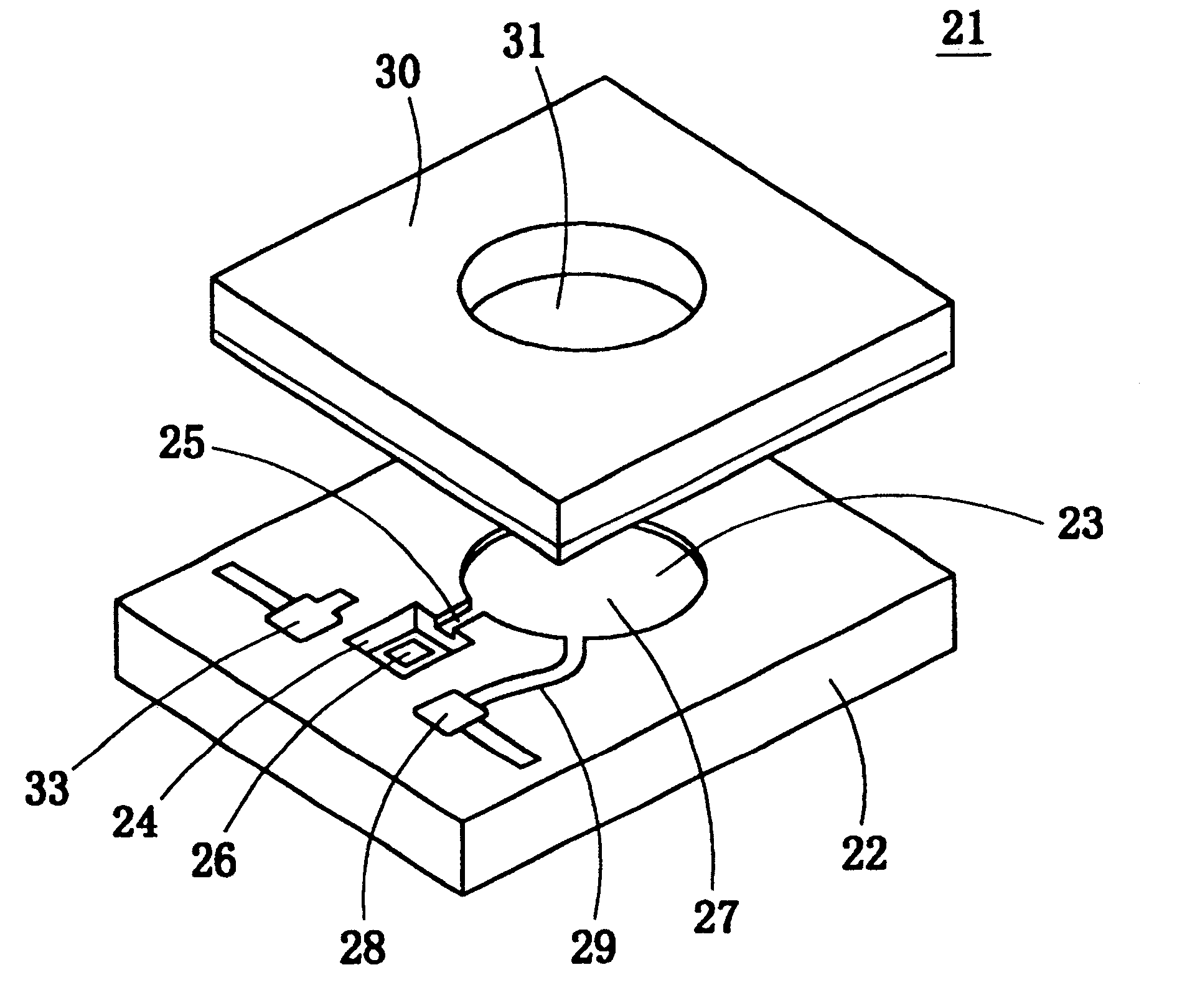
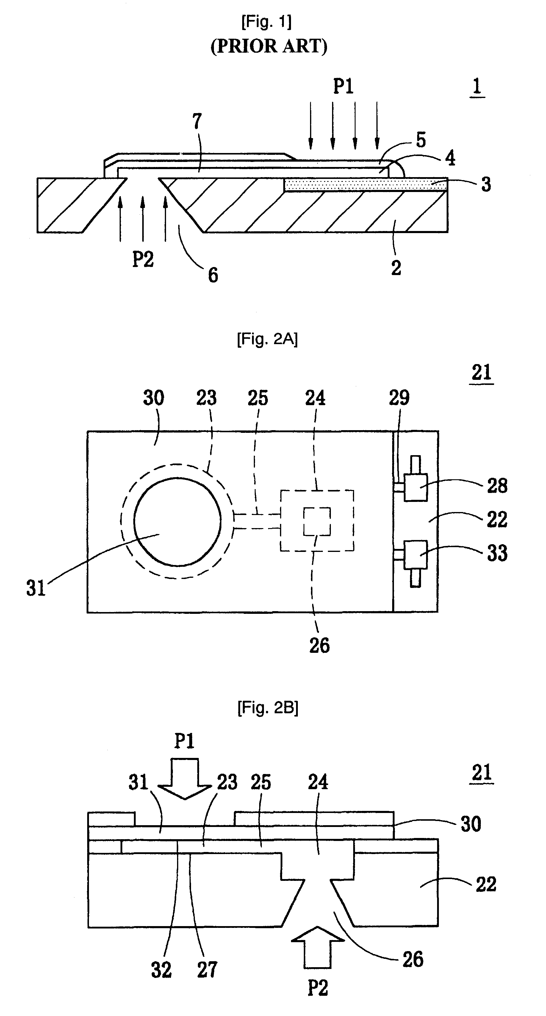
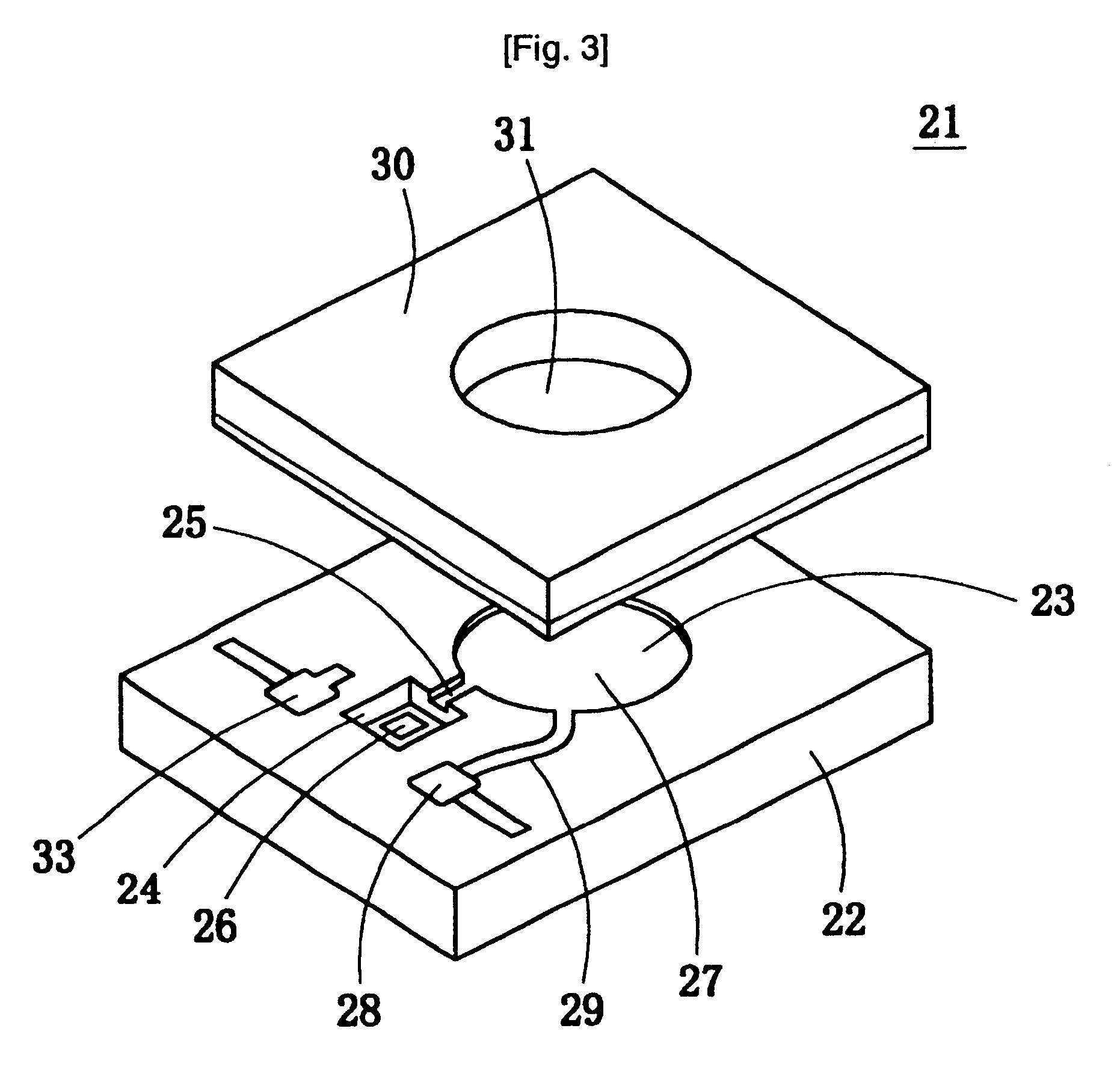
A pressure-detecting chamber 23, a pressure-directing path 25 and a buffer space 24 are formed on the upper face of a main-body-side substrate 22 as recessed portions, and the upper face of the pressure-detecting chamber 23 is covered with a thin-type diaphragm 31, and upper faces of the pressure-directing path 25 and the buffer space 24 are covered with a cover substrate 30. A pressure-introducing unit 26 formed on the lower face of the main-body-side substrate 22 is connected to the lower face of the buffer space 24. The cross-section of the buffer space 24 is greater than the cross-section of the pressure-introducing unit 26, and the capacity of the buffer space 24 is greater than the capacity of the pressure-directing path 25. With this arrangement, it is possible to provide a pressure sensor which can control the response characteristic of the pressure sensor to a pressure change with high precision without causing serious adverse effects on the other characteristics of the pressure sensor, without preventing the miniaturization of the sensor.

Description

BACKGROUND OF INVENTIONThe present invention relates to a pressure sensor and a pressure-measuring apparatus. In particular, the present invention concerns a pressure sensor which detects a pressure by detecting a distortion of a thin-film diaphragm due to an introduced pressure, and a manufacturing method of such a pressure sensor. Moreover, it also concerns a pressure-measuring apparatus using such a pressure sensor.FIG. 1 is a cross-sectional view that shows a structure of a conventional semiconductor pressure sensor of a relative-pressure type (Japanese Patent Application National Publication No. 8-501156). In this semiconductor pressure sensor 1, a doping area 3 that has a conductive type reversed to the substrate 2 is formed on a semiconductor substrate 2, and a diaphragm 5 is formed with a pressure-detecting chamber 4 located in between. Moreover, a pressure-introducing unit 6, which is formed in the semiconductor substrate 2 through antistropic etching, is connected to a pre...

Claims


Application Information

Patent Timeline
Patent Type & Authority Patents(United States)
IPC IPC(8): A61B5/022G01L9/00G01L9/12G01L7/00G01L9/04H01L29/84
CPCA61B5/022G01L9/0042G01L9/0073
Inventor KIMURA, ISAMUOBA, MASATOSHIITAKURA, TAKASHI
Owner ORMON CORP
Learn More