Electrochemical capacitor and method for making the same

a technology of electrochemical capacitors and capacitors, applied in the field of high-capacity electric capacitors, can solve the problems of increasing the internal resistance of the capacitor, reducing the electric capacity of the capacitor, and suffering from a number of technical and economic limitations

Inactive Publication Date: 2003-07-15
BELYAKOV ALEXEI I +4
View PDF7 Cites 13 Cited by
  • Summary
  • Abstract
  • Description
  • Claims
  • Application Information

AI Technical Summary

Benefits of technology

Such an embodiment of the banks makes it possible to reduce the volume and mass, as well as the internal electrical resistance of the capacitor bank by decreasing the number of collector plates.
The chosen directions of the conductivity anisotropy and their relative value make it possible to adjust the resistance of the conductor.

Problems solved by technology

Though the above-described designs on the whole provide for the realization of a new method of storing electric energy in electrochemical capacitors in their double electric layer on the developed surface of the electrodes, they suffer from a number of technical and economic limitations:
during long-term service the electric contact between the activated carbon particles in the paste-like electrode inevitably deteriorates, and this also leads to an increase of the internal resistance of the capacitor and to a decrease of its electric capacity;
the use of the paste-like electrode involves serious difficulties in making a section having a large area, so that the field of application of this design is limited to small-size capacitors having a low power capacity (less than 10-100 J); the solid electrode is brittle and breaks easily;
This leads to an increase of the leakage current and to the formation of gases owing to electrolysis of the released electrolyte, whereby the capacitor service life is shortened and its reliability is impaired.
The capacitor design known heretofore fails to meet this requirement.
This prior art method involves appreciable difficulties in automating the process and requires the use of costly corrosion-resistant materials for carrying out the processes of drying, proportioning the components and paste, and their transportation; the electrochemical capacitor cannot be manufactured using one production line.
The method of shaping an electrode does not ensure introducing the same amount of activated carbon particles into the electrode, therefore the capacity of the bank of elements comprised in the capacitor features an appreciable spread, this leading to an appreciable voltage redistribution in the bank when charging the block of series-connected elements.

Method used


Image

  • Electrochemical capacitor and method for making the same
  • Electrochemical capacitor and method for making the same
  • Electrochemical capacitor and method for making the same

Examples


Embodiment Construction

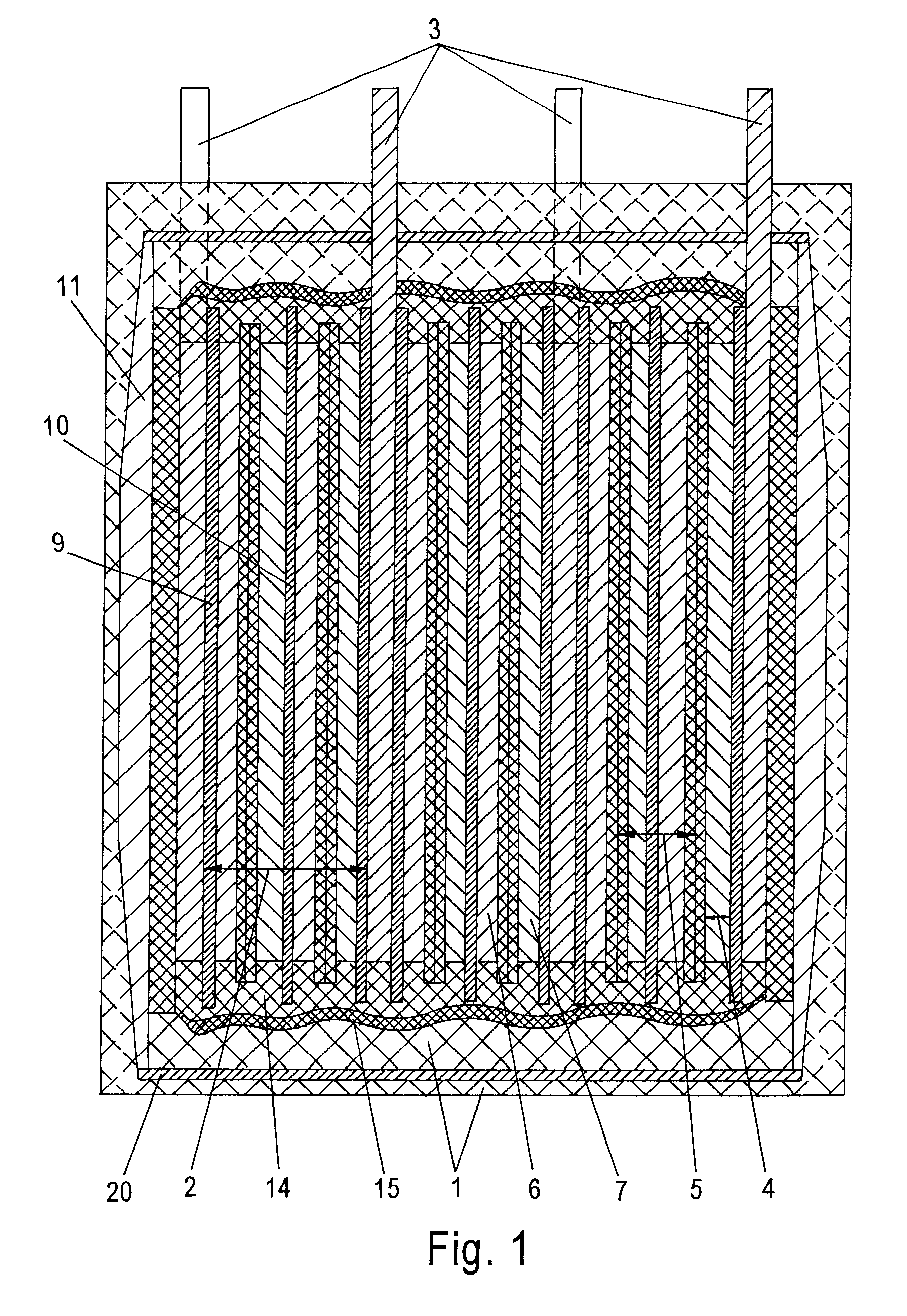
An electrochemical capacitor comprises a body 1 in which at least one bank of elements 2 is arranged. Leadouts 3 are connected to the bank (or banks).

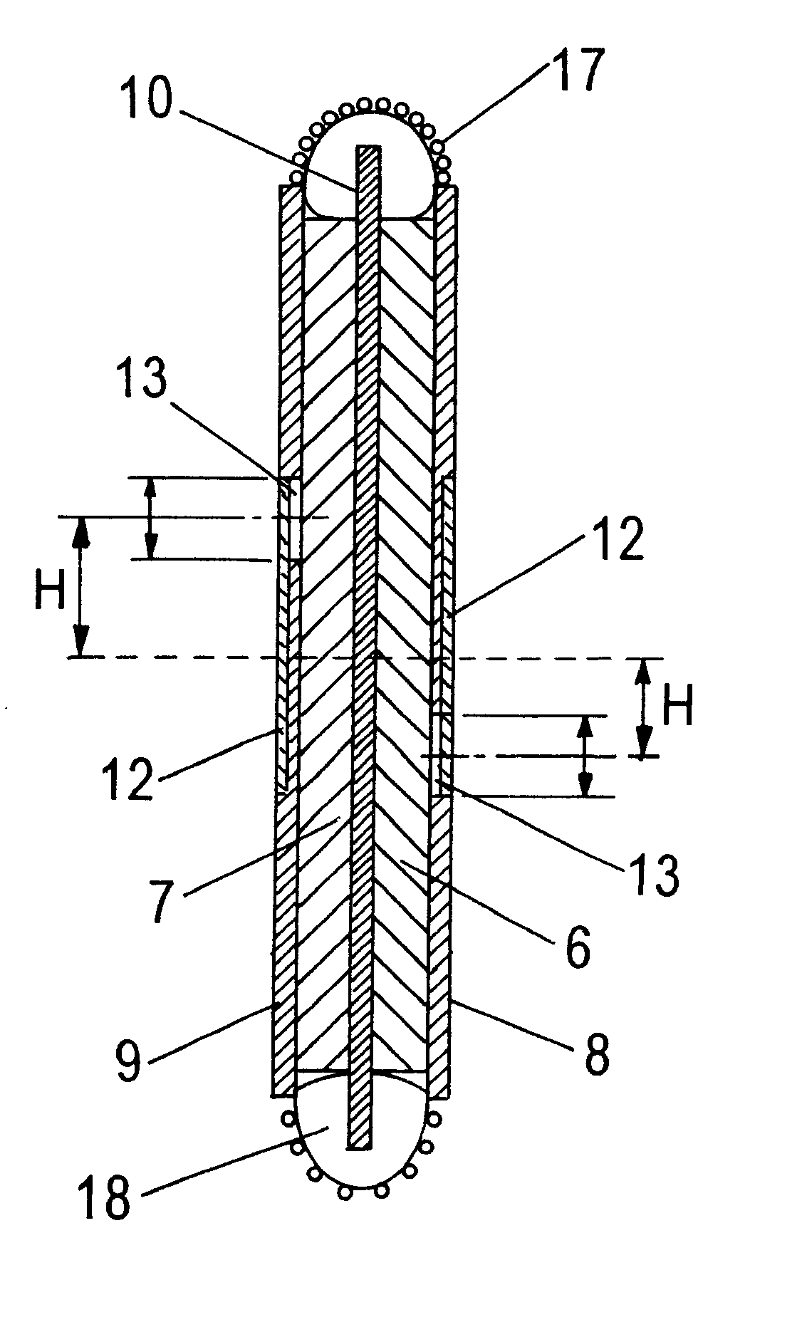
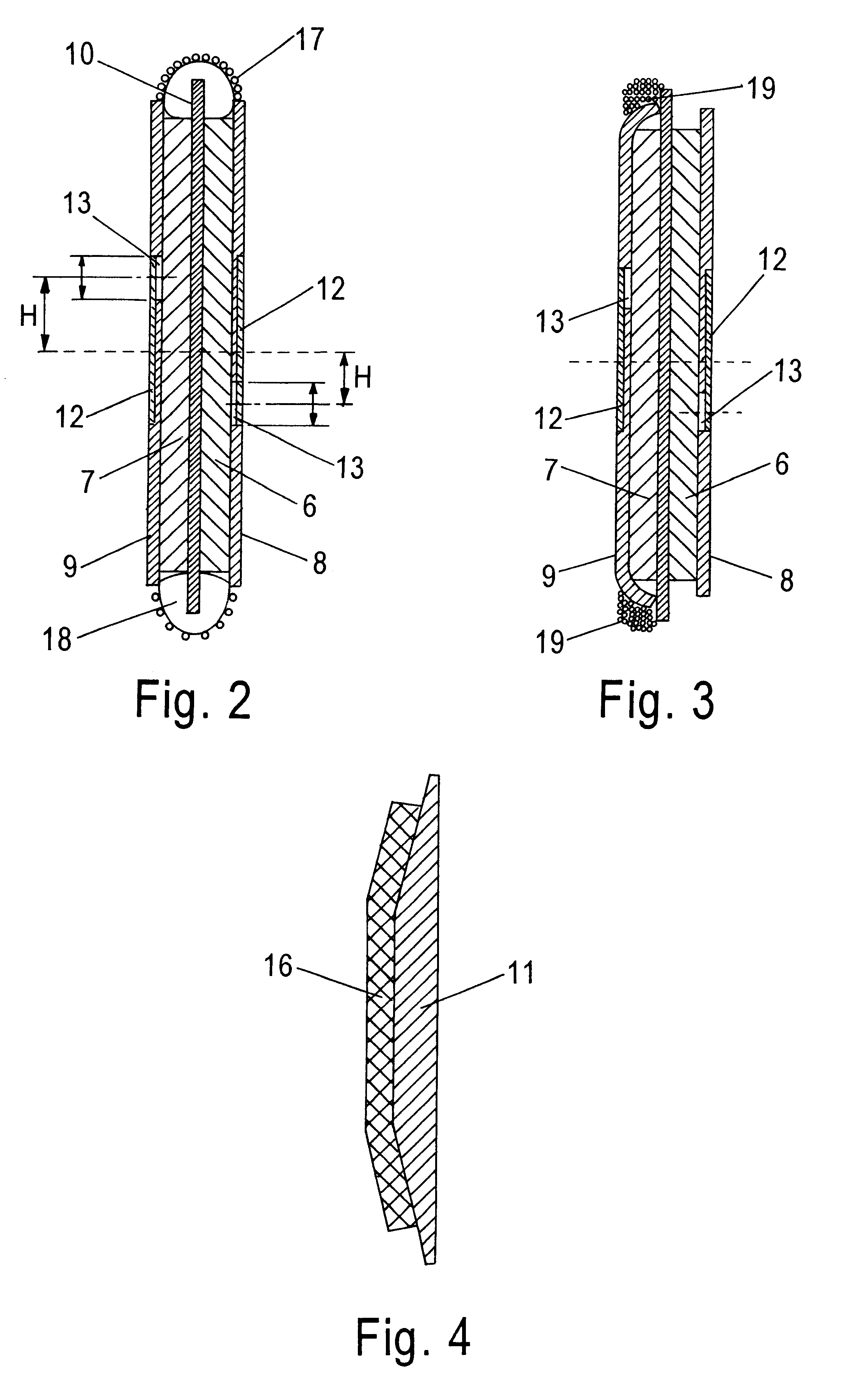
The bank of elements 2 consists of series-connected end elements 4 and internal elements 5, comprising porous electrodes 6 and 7 with activated carbon particles and a bulk collector (not shown) which comprises fine-dispersed particles of a non-carbon material (for instance, of carbonyl nickel), distributed uniformly in the bulk of the electrode (6 and 7).

Electron-insulating separators 8 and 9 are arranged on the electrodes 6 and 7, and an electron-conducting collector is disposed between the electrodes. The separators and electrodes are impregnated with an electrolyte.

The body 1 of the capacitor accommodates hold-downs 11 (interconnected, e.g. with the help of ties 20) with a resilient element 16, and also electron-conducting conductors 12 in ended for leveling-out the voltage in the series-connected elements of the bank 2. The conduct...


PUM


Abstract

A high-strength capacitor (1) for high-voltage charges includes a body having a set of elements (2) arranged therein as well as a plurality of current out puts (3) connected to said elements. The set of elements includes serially connected peripheral (4) and inner (5) elements which include porous electrodes (6,7) with a volumetric collector, isolation separators (8,9) as well as an electron conducting collector (10). In order to equalize the voltage in a set of serially connected elements, the body includes electron conductors connected together by clamps and arranged in openings (13) formed in each separator. The sets further include a cover (14) separated from the body by an additional layer (15). The body is self-supporting. The porous electrodes are elastic.

Description

This application claims priority of Russian Patent Application No. 98120015 filed Nov. 11, 1998.FIELD OF THE ARTThe present invention relates to high-capacity electric capacitors for storing electric energy and to methods of their manufacture, and more particularly to an electrochemical capacitor and to a method of manufacturing thereof.STATE OF THE ARTKnown in the art is a design of a capacitor with a double electric layer (U.S. Pat. No. 3,356,963), comprising a bank of storage sections arranged one on the other, connected in series and provided with insulators and current leadouts, each section having two porous electrodes impregnated with an aqueous electrolyte, said electrodes containing activated carbon particles and being separated by an electron-insulating porous separator. Each storage section has electron-conducting current-leading plates impervious for and inert to the electrolyte, encompassing the electrodes and connected with the separator over the periphery of the secti...

Claims


Application Information

Patent Timeline
Patent Type & Authority Patents(United States)
IPC IPC(8): H01G9/04H01G9/00H01G
CPCH01G9/008H01G9/02H01G9/08H01G9/035H01G4/04H01G11/58Y02T10/7022Y02E60/13Y02T10/70
Inventor BELYAKOV, ALEXEI I.BRYNTSEV, ALEXANDER M.ZVYAGINTSEV, MICHAIL S.ALEKHIN, VIKTOR G.KHODYREVSKAYA, NELYA V.
Owner BELYAKOV ALEXEI I
Why Eureka
Try Eureka