Mounting arrangement for auxiliary burner or lance

a technology of mounting arrangement and auxiliary burner, which is applied in the direction of manufacturing converters, furnaces, lighting and heating apparatus, etc., can solve the problems of limiting the mounting of burners in proximity to the melt, and reducing the efficiency of auxiliary burners

Inactive Publication Date: 2003-09-02
PROCESS TECH INT
View PDF10 Cites 69 Cited by
  • Summary
  • Abstract
  • Description
  • Claims
  • Application Information

AI Technical Summary

Benefits of technology

In one preferred embodiment, the mounting enclosure is a fluid cooled free standing block having a mounting aperture for a burner which extends the discharge opening of the burner past the step of the furnace. The preferred implementation of the mounting enclosure includes a front face adapted for the inner part of the furnace, a back face adapted to meet the side wall, and a width approximately that of the step between the side wall and the hearth of the furnace. In this manner, the mounting enclosure can rest on the step and be added to or removed from the furnace without any substantial change to the structure of the furnace. The mounting enclosure is manufactured from a material which is strong enough to withstand the scrap charging and steel and slag splashing of the furnace while also exhibiting a relatively high thermal conductivity. Preferably, the material used for the enclosure is cast iron which is inexpensive and can be easily produced with conduits for fluid cooling and the burner mounting aperture.
In a second preferred embodiment, the mounting enclosure is a fluid cooled box having a mounting aperture for a burner which extends the discharge opening of the burner past the step of the furnace. The preferred implementation of the mounting enclosure includes a front wall with a face adapted for the inner part of the furnace and side walls adapted to meet the furnace side wall of the furnace with a width approximately that of the step between the furnace side wall and the furnace hearth. The mounting enclosure is manufactured from a material which is strong enough to withstand the scrap charging and steel and slag splashing of the furnace while also exhibiting a relatively high thermal conductivity. Preferably, the material used for the mounting enclosure is copper which can be easily produced with conduits for fluid cooling and the burner mounting aperture.
According to another preferred embodiment of the invention, the mounting enclosure further includes a slanted porch between its front face and back face. The slant of the porch lessens the area of the front face directly in line with the radiation of the arc while providing an increased area for fluid cooling. Further, the slant of the porch allows scrap to slide down into the molten bath and away from the mounting enclosure. Optionally, slag retaining means, preferably in the form of cast channels or corrugations, are provided on the porch and the sides of the mounting enclosure to retain a covering of the splashed slag to form a protective barrier over the enclosure.
A first mounting arrangement includes utilizing the mounting enclosure to mount a burner, lance or similar apparatus in a furnace, preferably a burner, lance or similar apparatus with at least supersonic lancing capability and preferably in an electric arc furnace. The burner or lance is mounted by passing it through an aperture in a water cooled side panel aligned with the mounting aperture in the mounting enclosure. Because the mounting enclosure is approximately the width of the step, the discharge opening of the burner is moved by that distance closer to the center of the furnace. The flame discharge opening will now also extend past the inner edge of the sill so that the burner flow pattern is not such a problem to the hearth material and other furnace equipment mounted nearby.
The radiation from the arc increases according to the square of the distance as apparatus is moved closer to the center of the furnace. The mounting enclosure protects the apparatus from this harsh environment while it is located nearer the melt surface and center of the furnace while locating its discharge opening beyond the step to eliminate furnace structure considerations on the burner size and mounting particulars.
According to another aspect of the invention, locating the burner discharge opening nearer the center of the furnace by extending along the step with the mounting enclosure also has the advantage of producing a point of impingement for the oxidizing gas which is closer to the center of the furnace for the same angle and height above the surface. This means more of the oxidizing gas can react with the melt at earlier times in the melting and refining cycle and less reacts with the hearth and other related furnace parts on the outer edge of the process.

Problems solved by technology

While this advantageous to some extent, an excess of oxidizing gas is detrimental to the furnace components and the higher pressures needed for the larger nozzles rapidly become uneconomic.
However, there has been a limit to the mounting of the burners in proximity to the melt because of the structure of many present day furnaces.

Method used


Image

  • Mounting arrangement for auxiliary burner or lance
  • Mounting arrangement for auxiliary burner or lance
  • Mounting arrangement for auxiliary burner or lance

Examples


first embodiment

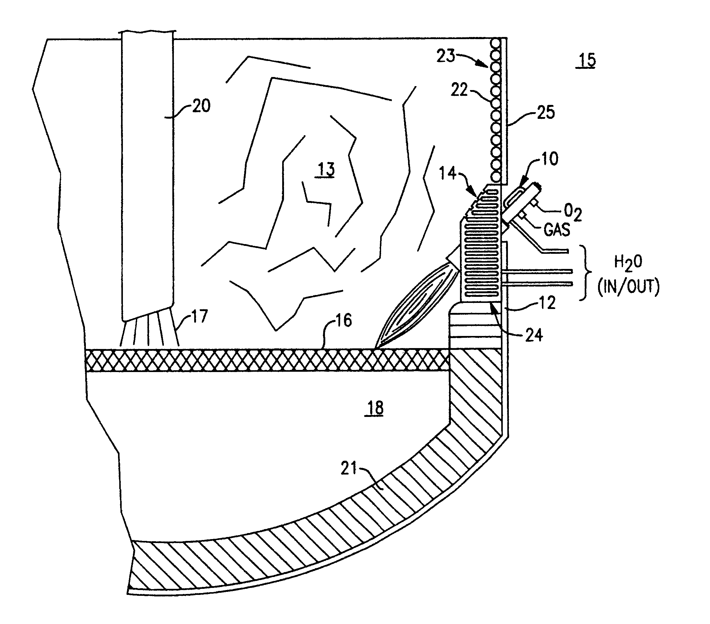
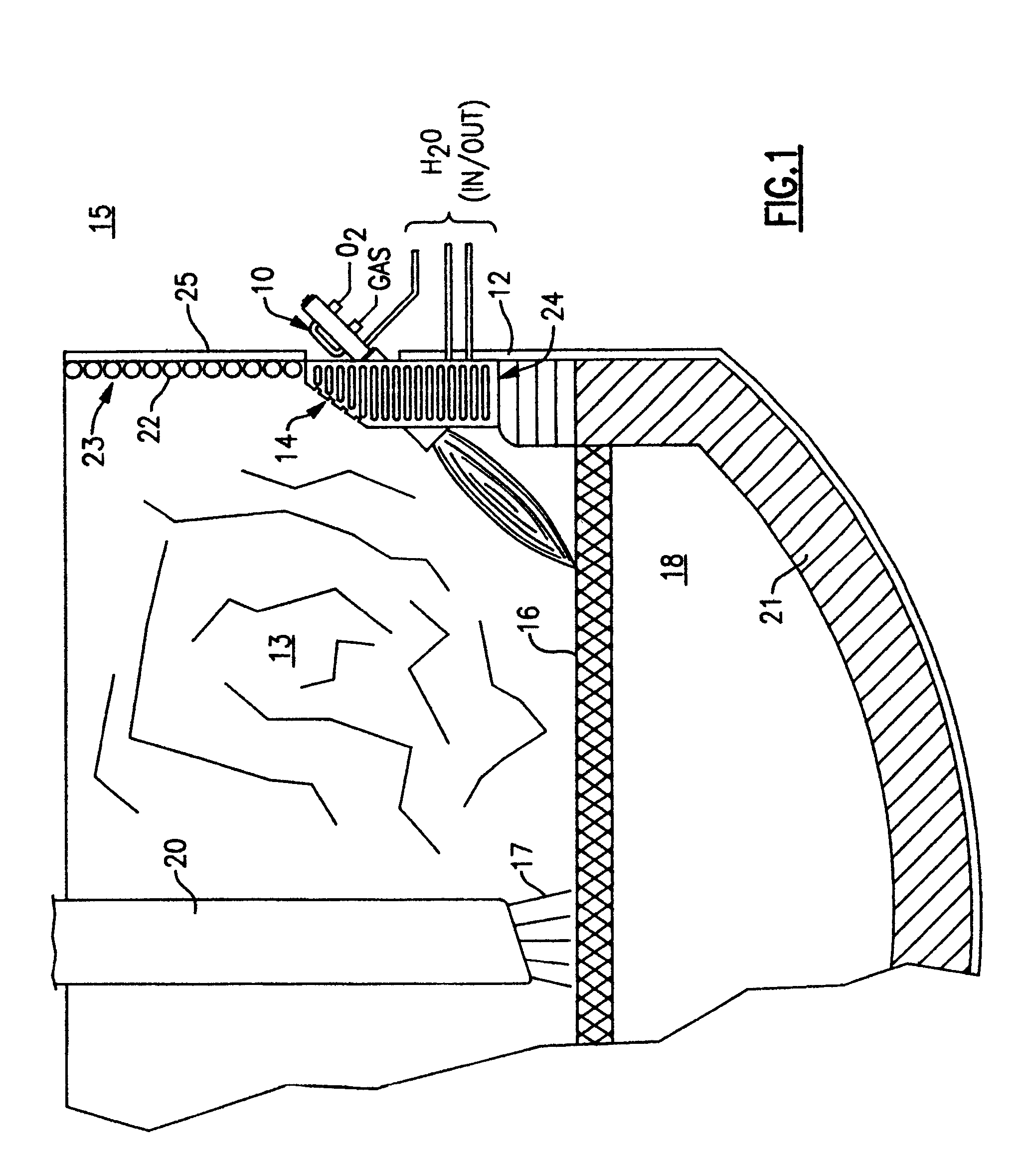
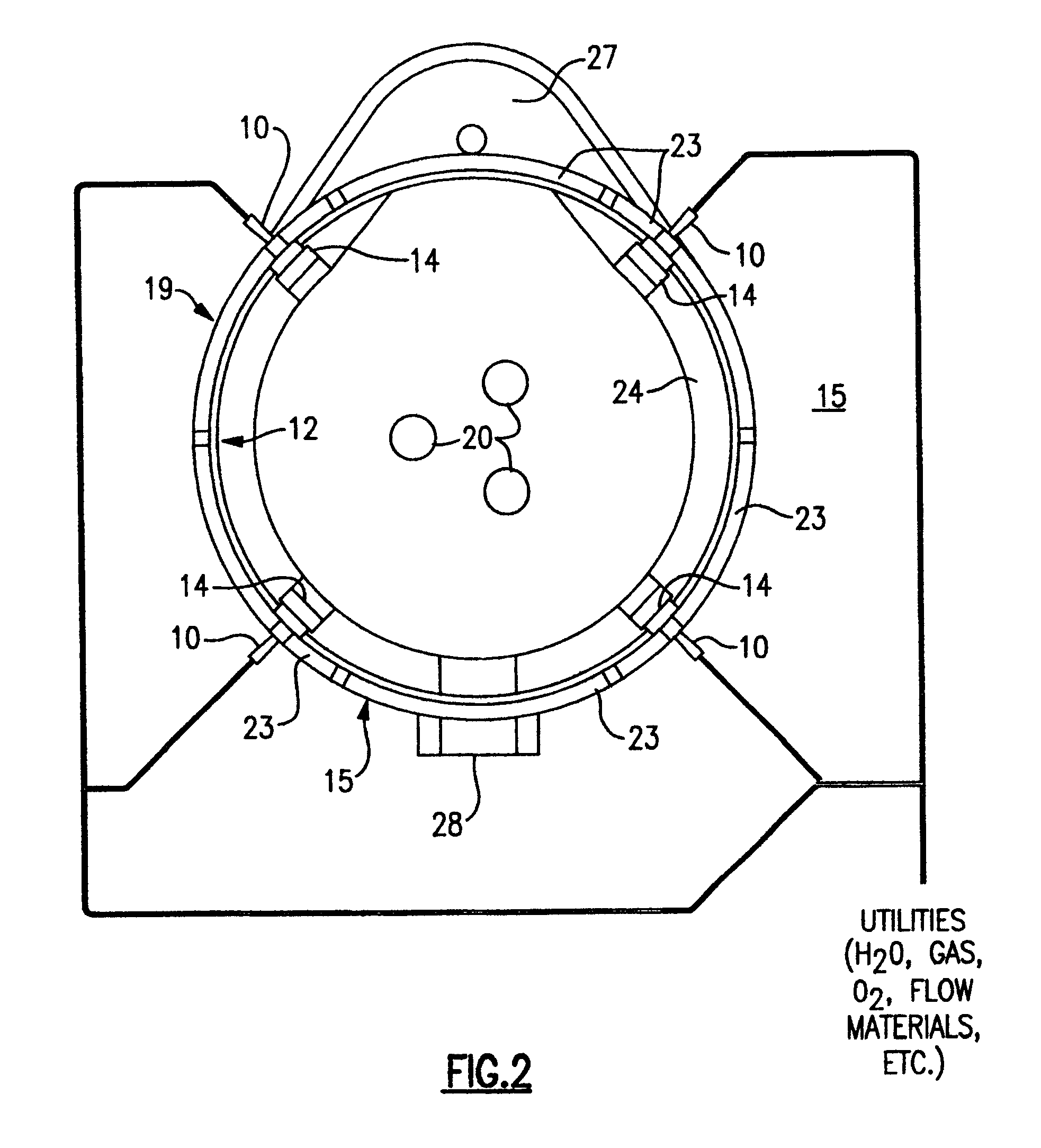
the mounting enclosure 14, as seen in one detailed embodiment in FIGS. 3-6, is a generally rectangular cast iron block with a front face 32 for facing the inside of the furnace and back face 36 for abutting the water cooled panel 23 of the furnace upper shell 19. The faces 32, 36 can be flat for ease of manufacture or curved to better conform to conventional circular furnace structure. The thickness of the sides 40 of the mounting enclosure 14 is approximately the width of the refractory of the step 21 so that it can rest on the step with its back face adjacent the side wall panel 23 or furnace upper shell and be self supporting without major structural change to the furnace 15. A mounting aperture 26 is cast at the desired angle of mounting for the burner 10 and is aligned with the opening in the water cooled panel 23. The burner 10 slide mounts into the apertures until its discharge end extends just past the step where it can deliver combustion products, injected materials or, imp...


PUM

PropertyMeasurementUnit
mounting angleaaaaaaaaaa

Abstract

A mounting enclosure and an improved mounting arrangement for apparatus used in metal melting, refining and processing, particularly those apparatus adapted for steel making in an electric arc furnace, such as burners, lances and the like with supersonic oxygen lancing capability and injectors or the like for the introduction of particulate matter. The mounting enclosure is fluid cooled to survive the hostile environment of the electric arc furnace and is designed to occupy the step between the side wall and hearth of the furnace without any substantial change to the structure of the furnace. The mounting enclosure comprises a plurality of fluid cooling conduits surrounding an apparatus aperture and an injector aperture which are formed through the enclosure and adapted to mount an apparatus and an injector. The mounting arrangement includes utilizing the mounting enclosure to mount an apparatus with supersonic oxidizing gas lancing capability and an injector for particulate carbon in an electric arc furnace. Because the mounting enclosure is approximately the width of the step, the discharge openings of the apparatus and the injector are moved closer to the surface of the melt and toward the center of the furnace thereby providing increased efficiency. The discharge openings will now be extended to near the edge of the step so that the oxidizing gas flow pattern of the apparatus does not degrade the hearth material or other furnace equipment mounted nearby and the carbon flow pattern of the injector sufficiently agitates the slag to produce foaming.

Description

1. Field of the InventionThe present invention generally relates to an improved mounting enclosure and mounting arrangement for apparatus used in metal melting, refining and processing, for example, steel making in an electric arc furnace (EAF), and more particularly, to a mounting arrangement for an auxiliary burner or lance relatively close to a molten metal bath to increase its efficiency.2. Description of Background ArtAn electric arc furnace makes steel by using an electric arc to melt one or more charges of scrap metal which is placed within the furnace. The scrap is charged by dumping it into the furnace through the roof from buckets which also may include charged carbon and slag forming materials. The arc melts the scrap into a molten pool of metal, called an iron carbon melt, which accumulates at the bottom or hearth of the furnace. After a flat bath has been formed by melting of all the scrap introduced, the electric arc furnace enters a refining or decarburizing phase. In...

Claims


Application Information

Patent Timeline
Patent Type & Authority Patents(United States)
IPC IPC(8): C21C5/00C21C5/46C21C5/52F27D1/12H05B7/18H05B7/00F27B3/22F27B3/20F27B3/10F27D9/00A61K38/00A61K9/20A61K38/43A61K38/49A61K38/57A61K45/00A61P7/02C07K7/06F27D99/00H05B7/22
CPCC21C5/5217F27D1/12F27D9/00H05B7/185C21C5/462C21C2005/4626F27B3/205F27B3/225F27D2009/0045A61P7/02Y02P10/20
Inventor SHVER, VALERY G.
Owner PROCESS TECH INT
Why Eureka
Try Eureka