Electric supply unit for plasma installations

a technology for plasma installations and power supply units, applied in emergency protective arrangements for limiting excess voltage/current, emergency protective arrangements for automatic disconnection, ac-dc conversion, etc., can solve the problems of reducing the efficiency of the system, requiring a comparatively long time,

Inactive Publication Date: 2003-09-16
HUETTINGER ELEKTRONIK
View PDF8 Cites 119 Cited by
  • Summary
  • Abstract
  • Description
  • Claims
  • Application Information

AI Technical Summary

Problems solved by technology

The disadvantage of the circuits known from these prior art documents is the fact that after re-activation of the operating voltage the system requires a comparatively long time until it is capable again "to sputter with full power" or to process the target

Method used


Image

  • Electric supply unit for plasma installations
  • Electric supply unit for plasma installations
  • Electric supply unit for plasma installations

Examples


first embodiment

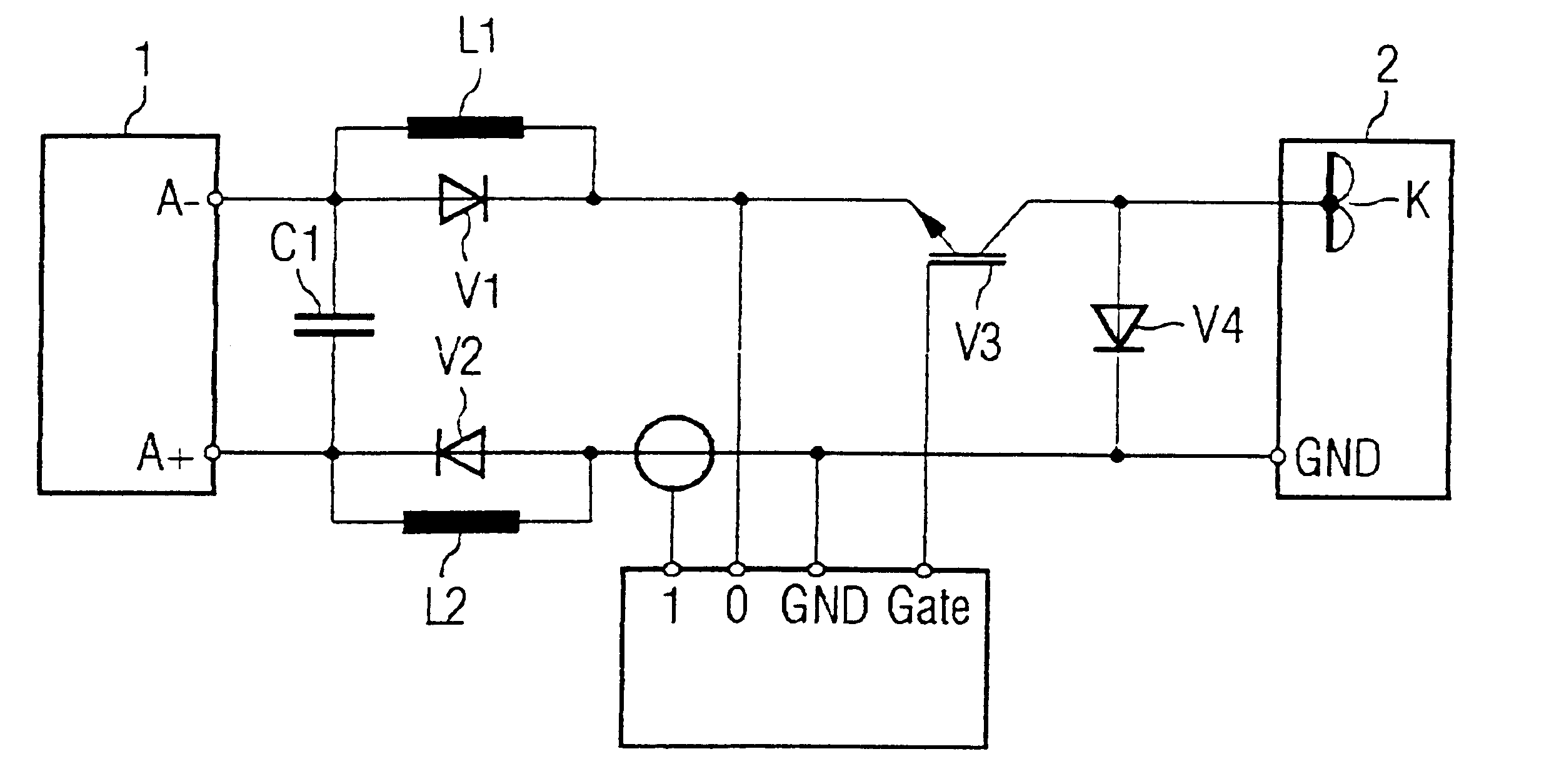
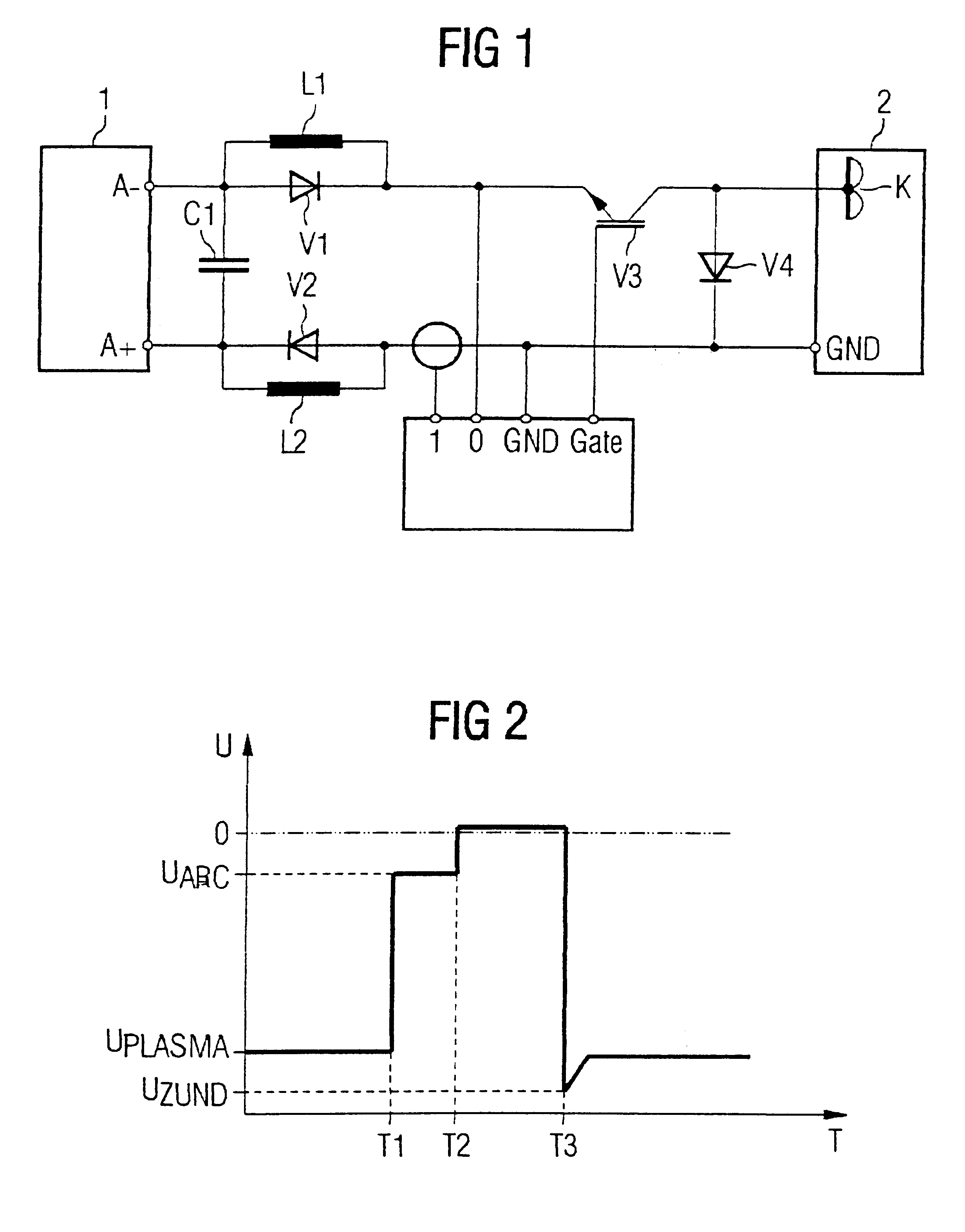
FIG. 1 illustrates the invention. The power supply unit comprises a switching-controller supply unit 1 that furnishes, for instance (i.e. without restriction of the general applicability) a d.c. voltage of roughly 400 V. The negative output terminal A-of the supply unit 1 is connected via an inductive resistor L1 and a power switch V3 configured as series switch to a cathode K in a plasma chamber 2 having a grounded housing. In the illustrated embodiment the series switch 1 is an IGBT element. The positive output terminal A+of the power supply unit 1 is connected via an inductive resistor L2 to the housing of the plasma chamber 2. This is symbolically indicated by GND.

In accordance with the invention, diodes V1 or V2, respectively, are connected in parallel with the inductive resistors L1 and L2, which are polarised in such a form that they are inhibiting during plasma operation.

Moreover, a capacitor C1 is connected between the output terminals A-and A+. A diode V4 is connected betw...

second embodiment

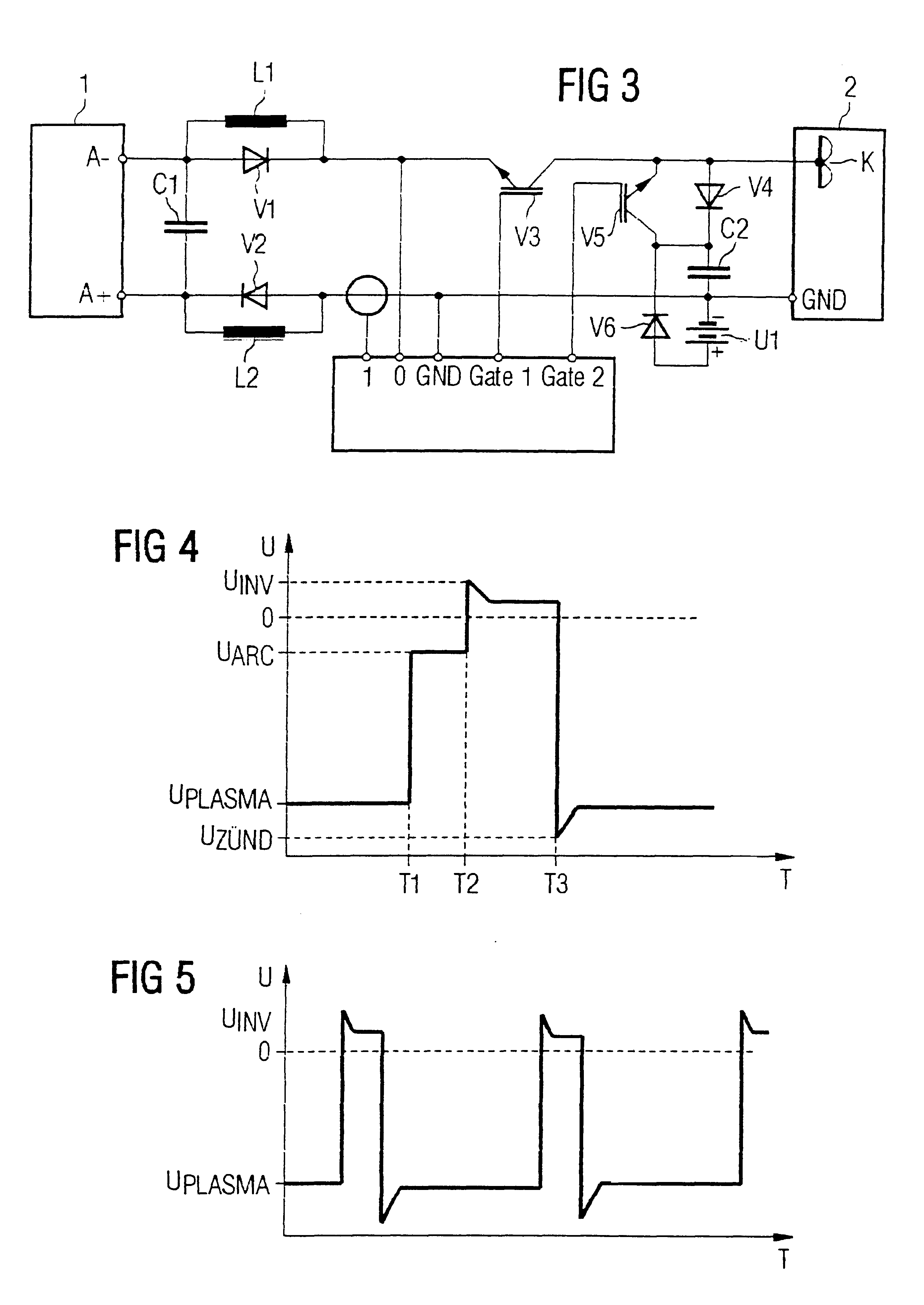
The mode of operation of the second embodiment according to FIG. 3 will be explained in more details in the following with reference to FIG. 4 illustrating a voltage / time diagram.

Upon occurrence of an electric arc (time T1) the voltage collapses from the plasma voltage UPlasma to the voltage UArc of the electric arc. In response, the circuit 3 opens the power switch V3. By means of the capacitor C2 connected in series with the diode V4, the energy resulting from the line inductance and the current is re-charged as voltage into the capacitor C2. By the time T2 this voltage is applied as inverted voltage to the electrodes of the plasma chamber 2 so that the electric arc is extinguished substantially more rapidly than in the case without active extinction. Due to the optional voltage source U1 the applied inverted voltage can be increased.

When the circuit 3 is provided with an additional pulse generator it is possible to commute the voltage applied to the plasma chamber not only upon o...

third embodiment

FIG. 6 shows the circuit of the invention wherein two cathodes K1 and K2 are disposed in the plasma chamber 2, which are each associated with a separate power switch V3 or V5 and a diode V4 or V6.

When the power switches V3 and V5 are turned on simultaneously the two cathodes are operating in parallel. When the two switches are turned on in alternation it is possible to control the effective performance of the cathodes by varying the connexion intervals. Commutation frequencies up to several kHz are possible.

FIG. 7 illustrates a voltage / time diagram wherein the alternating connexion of the two switches is schematically illustrated. It is, of course, also possible to use more than two cathodes.


PUM


Abstract

What is described here is a power supply unit for plasma systems such as plasma processing or coating devices, wherein electric arcs or disruptive breakdown may occur, which originate from an electrode in particular, comprisinga d.c. voltage or direct-current source whose output terminals are connected via an inductive resistor and a power switch to the electrodes of the plasma system, and possiblya circuit for detecting electric arcs or disruptive breakdown, that operates the switch upon occurrence of an electric arc or disruptive breakdown, in such a way that electrical energy producing a plasma will no longer be applied to the electrodes.The invention is characterised by the provisions that the inductive resistor(s) is (are) each connected to a recovery diode and that the switch is a series switch.In another embodiment of the invention a controller or closed-loop controller, respectively, is provided which, upon occurrence of an electric arc or disruptive breakdown, respectively, extinguishes same by disconnecting the voltage applied to the electrodes or by commutation to an inverted voltage for a defined period of time (deactivation interval), and which, upon occurrence of at least one electric arc or disruptive breakdown event, reduces the activation interval of the voltage causing plasma operation.

Description

The present invention relates to an electric power supply unit for plasma systems such as plasma-processing or coating devices wherein electric arcs or arcing may occur, particularly between the electrodes, in accordance with the introductory clauses of the independent Patent Claims.Plasma systems for which the electric power supply units of the claimed general type are intended are suitable for a great number of potential applications and are employed, for instance, for target sputtering. As a rule, they produce an electrical power ranging from roughly a few kW up to more than 100 kW. In typical cases, the operating voltages applied to the electrodes is in the range of 400 VV. Variations in the upward or downward direction--also as a function of the respective application--are, of course, possible.Specifically in so-called "reactive" sputtering, a technique applied, for instance, for the production of oxide or nitride films, or in the application of reactive gases problems occur as...

Claims


Application Information

Patent Timeline
IPC IPC(8): H01J37/32
CPCH01J37/32027H01J2237/0206
Inventor ZAHRINGER, GERHARDWIEDFMUTH, PETERRETTICH, THOMAS
Owner HUETTINGER ELEKTRONIK
Why Eureka
Try Eureka