High gain laser amplifier

a laser amplifier and high gain technology, applied in the direction of laser details, active medium materials, active medium shape and construction, etc., can solve the problems of high gain and high etendue in these conventional, non-guided, optical amplifiers, inherently conflicting requirements, and limited gain of these conventional optical amplifiers

Inactive Publication Date: 2003-11-11
RAYTHEON CO
View PDF7 Cites 15 Cited by
  • Summary
  • Abstract
  • Description
  • Claims
  • Application Information

AI Technical Summary

Problems solved by technology

Unfortunately, high gain and high etendue in these conventional, non-guided, optical amplifiers are inherently conflicting requirements.
Although the gain of these conventional optical amplifiers is in textbook theories limited by amplified spontaneous emission, in practice it is typically limited by the onset of parasitic oscillations involving reflections from the boundaries of the gain medium or other nearby surfaces.
In optical systems where phase conjugation is used, however, this issue is effectively circumvented, and the advantages of the guided amplifiers come to the foreground.
Fiber amplifiers also fall into the category of being guided amplifiers, but high-etendue devices have not been fabricated.
In any event, the performance of guided devices can also be limited by parasitic oscillation.
The gain achievable from this device was reported to be limited, however, by parasitic oscillation around its circumference.
As mentioned above, the gain of practical optical amplifiers is limited by the onset of parasitic oscillation.
Large etendue makes guided amplifiers particularly susceptible to parasitic oscillation.
Previous end-pumping schemes have failed because of the parasitic oscillation issue.

Method used


Image

  • High gain laser amplifier
  • High gain laser amplifier
  • High gain laser amplifier

Examples


Embodiment Construction

Illustrative embodiments and exemplary applications will now be described with reference to the accompanying drawings to disclose the advantageous teachings of the present invention.

While the present invention is described herein with reference to illustrative embodiments for particular applications, it should be understood that the invention is not limited thereto. Those having ordinary skill in the art and access to the teachings provided herein will recognize additional modifications, applications, and embodiments within the scope thereof and additional fields in which the present invention would-be of significant utility.

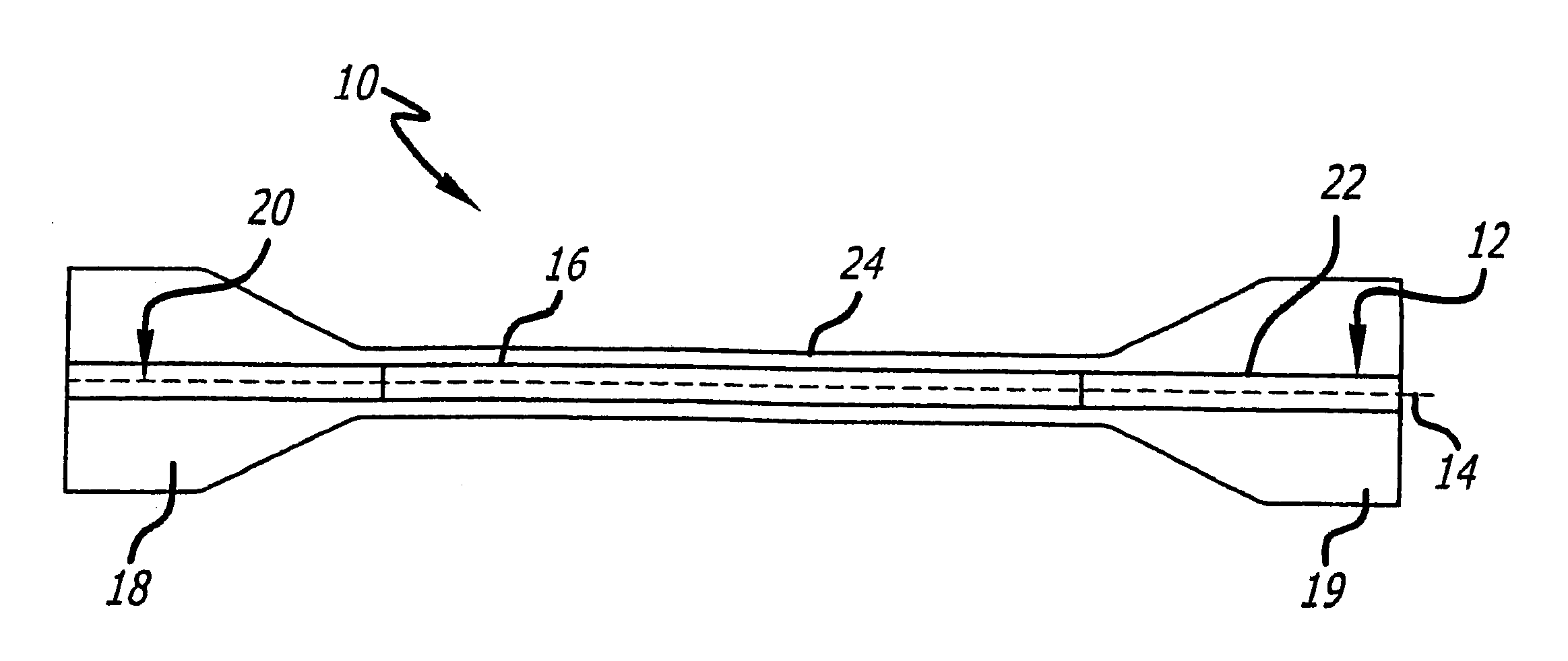
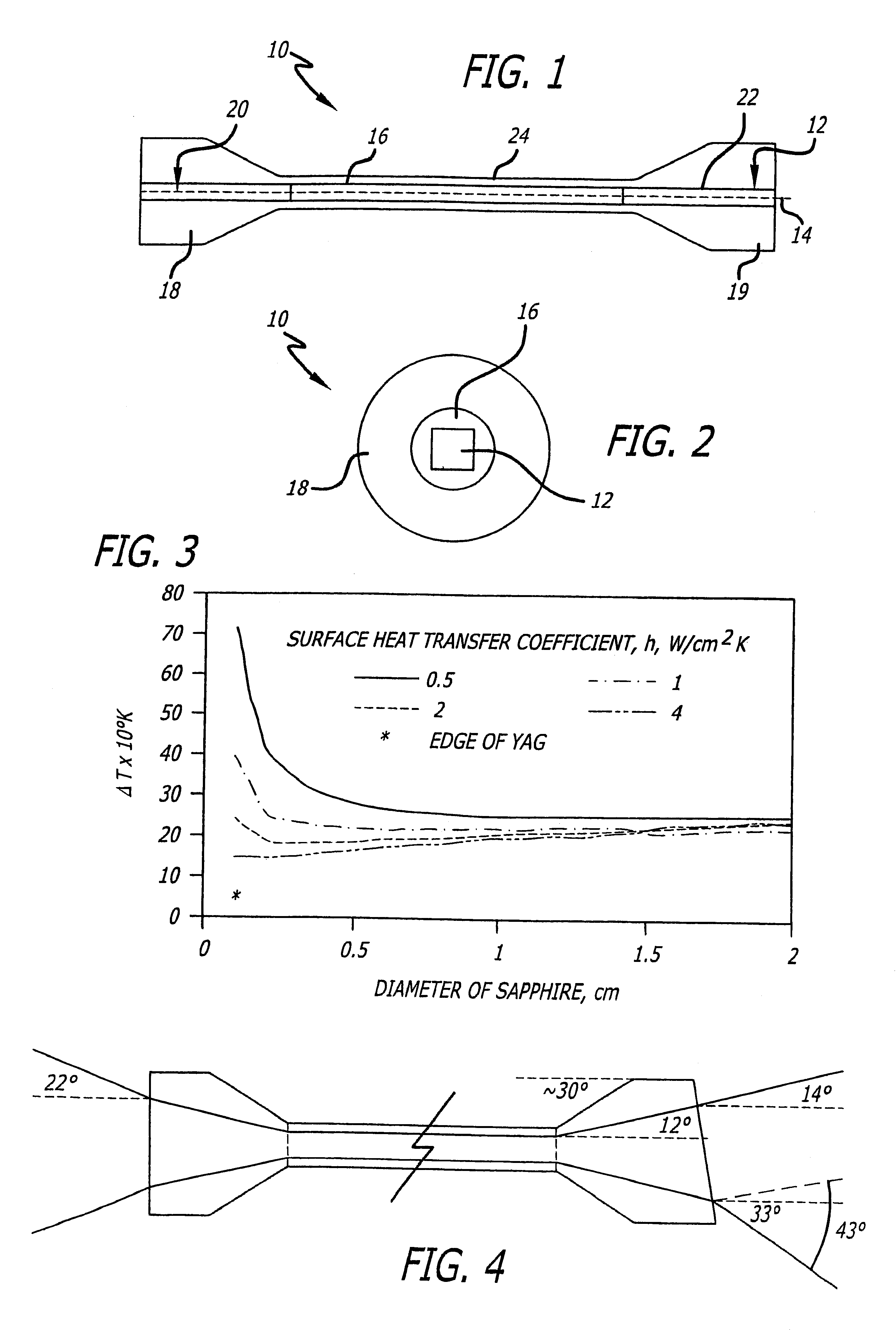
FIG. 1 is a sectional side view of an optical amplifier constructed in accordance with the teachings of the present invention. FIG. 2 is an end view of the optical amplifier of FIG. 1. The amplifier 10, includes a first crystal 12, having a geometric and propagation axis 14 associated with it, and having a first index of refraction n.sub.1. A second crystal 16 i...


PUM


Abstract

A high gain optical amplifier and method. Generally, the inventive amplifier includes a first crystal having an axis and a first index of refraction and a second crystal bonded to the first crystal about the axis and having a second index of refraction. The first index is higher than the second index such that light through the first crystal is totally internally reflected. In the illustrative embodiment, the first crystal is Yb:YAG with an index of approximately 1.82, the second crystal is Sapphire with an index of approximately 1.78, and the axis is the propagation axis. The invention is, in its preferred embodiment, a light guide fabricated out of crystalline materials, diffusion bonded together. If the core of the light guide is doped with laser ions, high gain amplifiers made be designed and operable over a large étendue. With a judicious choice of the laser crystal and cladding materials, shape, and bonding technique, the guided amplifier is much less susceptible to parasitic oscillation than amplifiers constructed in accordance with conventional teachings. The clad core is also able to handle larger thermal load without breakage than can an unclad core.

Description

1. Field of the InventionThe present invention relates to optical and other electromagnetic systems. More specifically, the present invention relates to high gain and high etendue optical amplifiers for use with lasers and other devices.2. Description of the Related ArtOptical amplifiers are used in many applications. Optical amplifiers are used as gain elements in lasers and in a number of other optical systems such as amplifiers per se in Master Oscillator Power Amplifiers (MOPAs), the amplifying component of loop phase conjugator systems, and as the nonlinear medium in optical four-wave mixing devices. In these and other applications, high gain at large etendue is often the enabling and most important design consideration. Etendue is defined as the product of the cross-sectional area of a beam and its full angular extent.The prior art for optical amplifiers can be divided into two categories: guided and unguided. With unguided amplifiers, etendue is maximized by adjusting the tra...

Claims


Application Information

Patent Timeline
Patent Type & Authority Patents(United States)
IPC IPC(8): H01S3/06H01S3/063H01S3/16
CPCH01S3/063H01S3/0602H01S3/0612H01S3/1643H01S3/1618H01S3/0617
Inventor BRUESSELBACH, HANS W.BETIN, ALEXANDER A.SUMIDA, DAVID S.
Owner RAYTHEON CO
Why Eureka
Try Eureka