Synthetic silica glass member, photolithography apparatus and process for producing photolithography apparatus

a technology of photolithography and silica glass, applied in the direction of photomechanical equipment, printers, instruments, etc., can solve the problems of limited lens materials used in illumination optical systems and projection optical systems, poor light transmittance for practical use, and strict limitations on the use of silica glass members made of silica glass alon

Inactive Publication Date: 2003-12-02
NIKON CORP
View PDF12 Cites 7 Cited by
  • Summary
  • Abstract
  • Description
  • Claims
  • Application Information

AI Technical Summary

Benefits of technology

A hydrogen molecule concentration of less than 1.times.10.sup.16 molecules / cm.sup.3 results in greater reduction in transmittance with prolonged irradiation with an ArF excimer laser. On the other hand, synthesis under conditions with a hydrogen molecule concentration of greater than 2.times.10.sup.18 molecules / cm.sup.3 tends to result in a higher .ident.Si--H concentration as well and greater initial irradiation absorption, and a non-uniform hydrogen molecule concentration in the silica glass.
According to the invention, the distribution range (variation width) is preferably small for the hydrogen molecule concentration value in the radial direction at any given point of the synthetic silica glass member. The radial direction is the direction along any desired plane in the member perpendicular to the direction of the incident irradiated beam. Specifically, for the hydrogen molecule concentration at the center of the member (geometrical center of gravity), the variation width V of the hydrogen molecule concentration at any desired point on the plane including this center preferably satisfies the condition represented by -50%.ltoreq.V.ltoreq.+50%, and more preferably satisfies the condition represented by -20%.ltoreq.V.ltoreq.+20%. Thus, with a small distribution range (variation width) for the hydrogen molecule concentration in the radial direction of the member, it is possible to achieve a stable exposure dose over a prolonged period without irregularity in the degree of reduction in transmittance at any point in the member in the radial direction of the member, even when the ArF excimer laser is irradiated thereon for a prolonged period.
As explained above, when the hydrogen molecule concentration exceeds 2.times.10.sup.18 molecules / cm.sup.3 the variation width of the hydrogen molecule concentration tends to be larger. In order to reduce the variation of the hydrogen molecule concentration, it is preferred to adjust the oxygen gas / hydrogen gas flow ratio to 0.25-0.40 for the total combustion gas (oxygen-containing gas and hydrogen-containing gas) ejected from the burner during the silica glass ingot synthesis step. If the flow ratio is within this range it will be possible to include the necessary number of hydrogen molecules in the silica glass to prevent reduced transmittance during prolonged irradiation of light, while also minimizing the degree of .ident.Si--H structure which is a cause of initial irradiation absorption, and to thereby reduce the variation width for the hydrogen molecule concentration; in addition, since the various conditions for the ingot synthesis step such as the synthesis burner shape, the raw material flow, the oscillating pattern of the target holding the ingot, etc., are also factors determining the hydrogen molecule concentration in the ingot and its variation width, the .ident.Si--H concentration, etc., appropriate adjustment of these conditions is preferred. For example, if the raw material flow is too high the center temperature of the flame falls, tending to result in easier hydrogen concentration distribution.

Problems solved by technology

However, when the light source emits light with a wavelength range in the ultraviolet region, and particularly in the region below 250 nm, the light transmittance is too poor for practical use when employing lens materials used in illumination optical systems and projection optical systems designed for light with a longer wavelength region than i rays.
Lens materials used in illumination optical systems and projection optical systems are therefore limited to silica glass and some crystal materials that exhibit high light transmittance.
Consequently, there have been strict limitations on silica glass members made of silica glass alone that can be used for photolithography apparatuses employing ultraviolet light from an excimer laser stepper as the light source.
To date it has been independently confirmed that the desired properties for an optical member used in a photolithography apparatus employing an ArF excimer laser or the like with a wavelength of 200 nm or less as the light source are a low loss factor before irradiation with an ArF excimer laser beam (wavelength: 193.4 nm) and low transmittance reduction even with prolonged irradiation with an ArF excimer laser (i.e. low prolonged transmittance variation); however, it has been difficult to obtain silica glass members satisfying both of these properties, and therefore no photolithography apparatus has existed with an ArF excimer laser employing such a member as the light source.
First, a lump of a size corresponding to the size of the synthetic silica glass member to be fabricated is cut out from the ingot and subjected to grinding.
This procedure is used because it is usually not possible to complete measurement of transmittance for all of the correction samples before the critical elapsed time [tm] has elapsed (and therefore calibration using formula (1) is not possible).

Method used


Image

  • Synthetic silica glass member, photolithography apparatus and process for producing photolithography apparatus
  • Synthetic silica glass member, photolithography apparatus and process for producing photolithography apparatus
  • Synthetic silica glass member, photolithography apparatus and process for producing photolithography apparatus

Examples


Embodiment Construction

) were in the range of -50%.ltoreq.V.ltoreq.+50%. The hydrogen molecule concentration value variation widths V of the samples of Comparative Examples 1 to 3 were all in a range larger than the range of -50%.ltoreq.V.ltoreq.+50%.

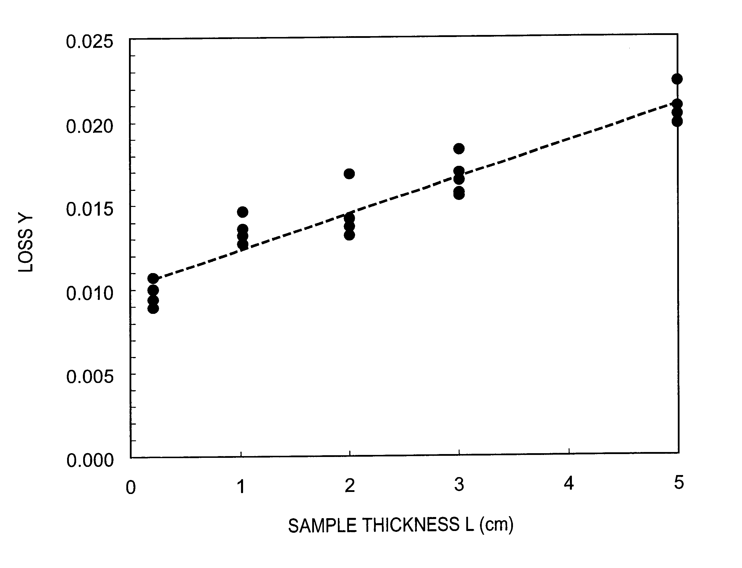
As confirmed by this mounting in steppers, Examples 1 to 9 which had loss factors (initial irradiation absorption) of no greater than 0.0050 cm.sup.-1 after ArF excimer laser irradiation at 1.times.10.sup.4 pulses exhibited performance suitable for practical use, while Comparative Examples 1 to 3 which had loss factors of greater than 0.0050 cm.sup.-1 after ArF excimer laser irradiation did not exhibit performance suitable for practical use. It was confirmed that those with an average hydrogen molecule concentration of 5.times.10.sup.18 / cm.sup.3 or greater as in Comparative Example 3 have a large hydrogen molecule concentration value variation width and a very large loss coefficient after 1.times.10.sup.4 pulse irradiation with an ArF excimer laser.

The hydro...


PUM

PropertyMeasurementUnit
wavelength rangeaaaaaaaaaa
wavelengthaaaaaaaaaa
specific wavelength rangeaaaaaaaaaa

Abstract

A photolithography apparatus has an exposure light source for emitting exposure light with a wavelength of 400 nm or less, a reticle with a pattern original image formed therein, an illumination optical system for illuminating the reticle with exposure light, a projection optical system for projecting the pattern image from the reticle onto a photosensitive plate and an alignment system for aligning the reticle and the photosensitive plate. At least some of the synthetic silica glass members composing the illumination optical system, the projection optical system and the reticle consist of synthetic silica glass members which, upon 1x10<4 >pulse irradiation with an ArF excimer laser at an energy density from 0.1 muJ / cm<2>.p to 200 mJ / cm<2>.p, have a loss factor no greater than 0.0050 cm<-1 >at 193.4 nm measured after irradiation, a hydrogen molecule concentration from 1x10<16 >molecules / cm<3 >to 2x10<18 >molecules / cm<3 >and a loss factor no greater than 0.0020 cm<-1 >before ultraviolet irradiation.

Description

This is a Continuation-In-Part application of International Patent Application serial No. PCT / JP01 / 02567 filed on Mar. 28, 2001, now pending.1. Field of the InventionThe present invention relates to a synthetic silica glass member, to a photolithography apparatus and to a process for producing the photolithography apparatus. More specifically, it relates to a synthetic silica glass member for a photolithography apparatus used in an optical system with lenses, mirrors and the like for photolithography technology, in a specific wavelength range of no greater than 400 nm and preferably no greater than 300 nm, to a photolithography apparatus constructed using such optical members and to a process for producing the photolithography apparatus.2. Related Background ArtPhotolithography apparatuses known as "steppers" (projection exposure apparatuses) are conventionally used for photolithography techniques which accomplish exposure and transfer of intricate patterns of integrated circuits on...

Claims


Application Information

Patent Timeline
Patent Type & Authority Patents(United States)
IPC IPC(8): C03C3/06G03F7/20G03F1/14C03B20/00G02B1/00G03F7/22H01L21/027
CPCC03C3/06G03F7/70958G03F7/70058G03F7/70216G03F1/14C03C2201/21G03F7/70191G03F7/70566G03F7/70558G03F7/70891
Inventor YOSHIDA, AKIKOKOMINE, NORIOJINBO, HIROKI
Owner NIKON CORP
Why Eureka
Try Eureka