Mixed-size packed beds

Inactive Publication Date: 2003-12-23
BECO ENG
View PDF30 Cites 20 Cited by
  • Summary
  • Abstract
  • Description
  • Claims
  • Application Information

AI Technical Summary

Benefits of technology

It is an object of the invention to provide a method and apparatus for mass or heat transfer between two fluids in the f

Problems solved by technology

The interstitial voids between packing elements can also create low-resistance by-pass routes for gas and liquid, causing liquid channeling as well as gas axial back-mixin

Method used


Image

  • Mixed-size packed beds
  • Mixed-size packed beds
  • Mixed-size packed beds

Examples


Embodiment Construction

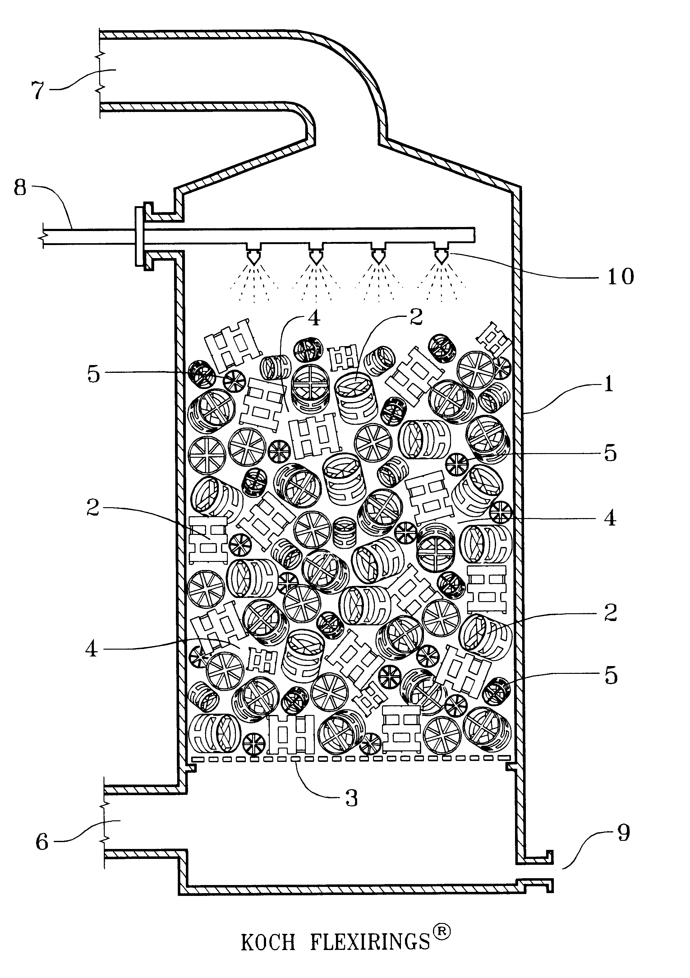
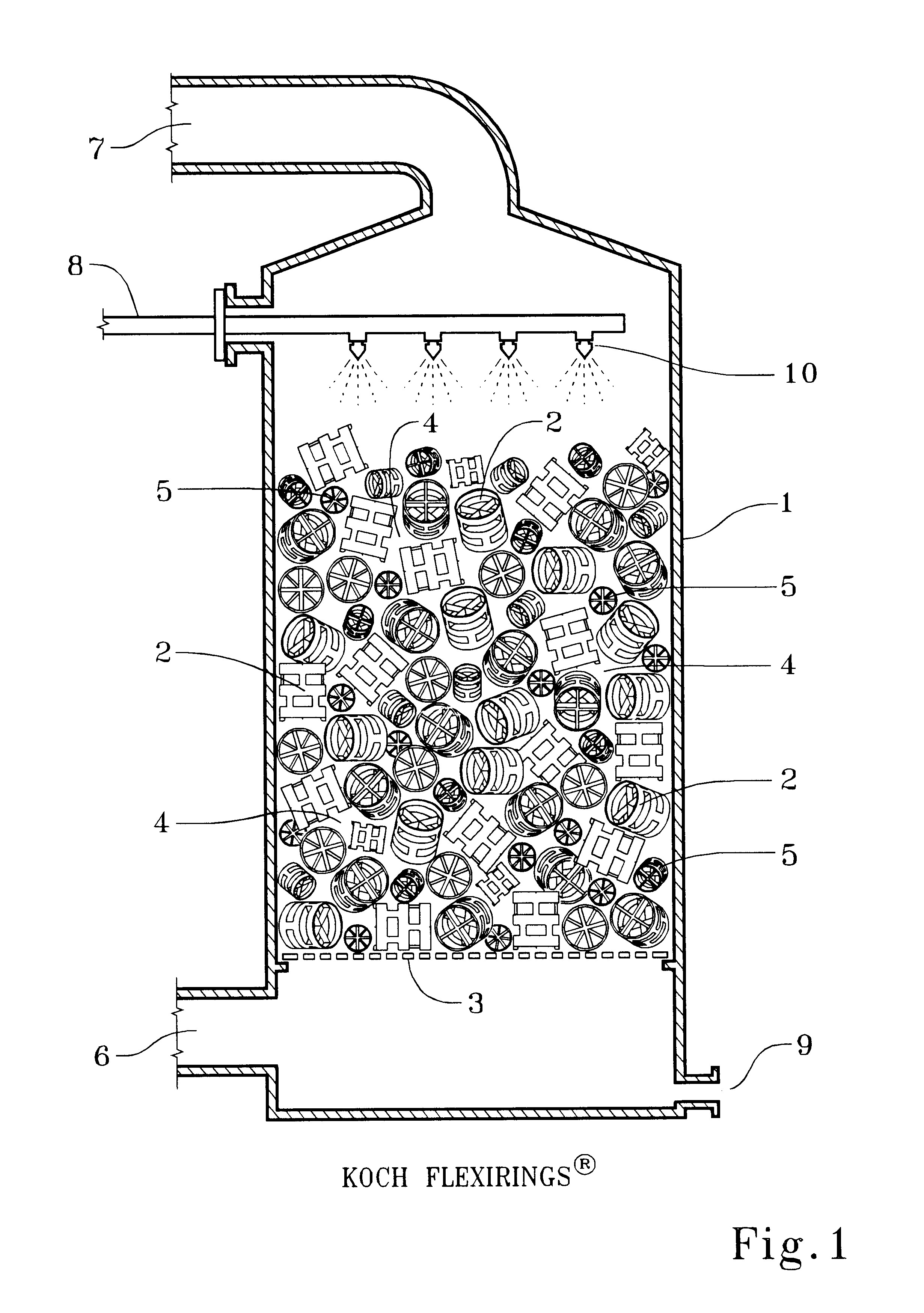
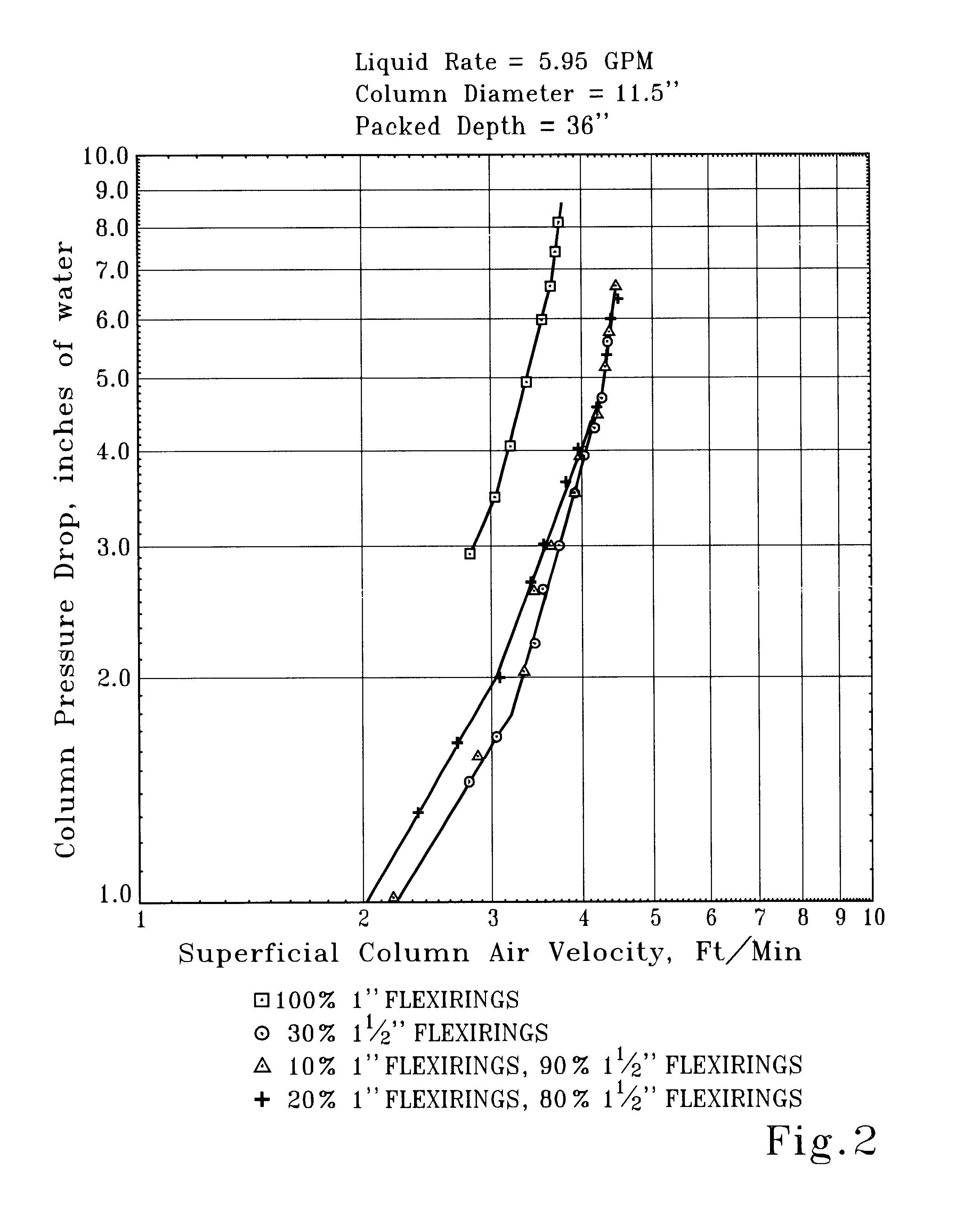
Testing of pressure drop as a function of air flow rate and limiting flow capacities was done for two different packing types: a "planar-surface" ring packing and a "filamentary" spherical packing. The packings tested included Koch Flexirings.RTM., a Pall ring type, and a spherical filamentary packing, Jaeger Tri-Packs.RTM.. An 111 / 2-inch inside diameter, vertical acrylic tube was used as the packed bed housing to allow visual observation of the gas-liquid interaction. Ambient air was blown up through the housing by means of a Cincinnati Size No. 15 centrifugal blower. The air flow rate was controlled by means of a throttling damper on the blower inlet and metered by means of a pitot tube located in a horizontal 61 / 4 inch diameter, 5-foot long, duct run from the blower discharge to the inlet of the test column. Pilot tube pressure differential was measured by means of an Ellison inclined draft gage. The air velocity through the vertical test section was calculated from the ratio of ...


PUM

PropertyMeasurementUnit
Fractionaaaaaaaaaa
Fractionaaaaaaaaaa
Fractionaaaaaaaaaa

Abstract

An improved random-dumped packed bed for effecting inter-phase heat and mass transfer. The packed bed is a plurality of a first packing size substantially uniformly mixed and co-mingled with a plurality of the suitable second larger packing size. The mixed bed so formed provides the additional surface area and mass transfer capacity of the plurality of the added first smaller packing size while maintaining the gas and liquid limiting flow capacity of a bed of the second larger packing size absent the smaller first packing size.

Description

This invention relates to packed bed assemblies of random-dumped packings used for mass and heat transfer operations between two fluids, typically operations such as gas absorption and desorption, distillation, liquid extraction, and the like.Extended-surface, random-oriented, packed beds for mass and heat transfer applications are widely used in industry, typically for gas-liquid and liquid-liquid contact. While most packed bed assemblies comprise vertical cylindrical columns employing countercurrent gas-liquid flow, referred to as packed towers, horizontal gas flow units are also known to the art, and are referred to as cross-flow contactors. To save energy and capital costs in either vertical or horizontal flow configurations, industry requires the highest flow capacities and lowest pressure drops for the packed bed contacting media. These objectives have been partially met in recent years primarily through the use of larger packing sizes.At equal gas and liquid flows or loading ...

Claims


Application Information

Patent Timeline
IPC IPC(8): B01J19/30B01D53/04
CPCB01D53/18B01J19/30Y10S261/72B01J2219/3083B01J2219/315B01J2219/30223
Inventor LERNER, BERNARD J.
Owner BECO ENG
Why Eureka
Try Eureka