Liquid crystal device and electronic apparatus

a liquid crystal device and electronic equipment technology, applied in the direction of instruments, propulsion parts, packaging, etc., can solve the problems of inability to recognize the display in the dark surroundings, inability to achieve satisfactory color development, and inability to achieve satisfactory contrast characteristics at the time of transmission type display, etc., to achieve high-quality reflection type

Inactive Publication Date: 2004-01-20
138 EAST LCD ADVANCEMENTS LTD
View PDF13 Cites 49 Cited by
  • Summary
  • Abstract
  • Description
  • Claims
  • Application Information

AI Technical Summary

Benefits of technology

In this construction, it is possible to form on the first substrate a laminate in which a transflective layer, an insulating layer, a color filter, a protective layer and a transparent electrode layer are stacked together, and it is possible to protect the transflective layer with the insulating layer and to protect the color filter with the protective layer and, further, to perform a reflection type color display using external light and a transmission type color display utilizing an illuminating device.
In the form in which an insulating layer is also stacked in the laminate, it is possible to further provide an active element formed on the insulating layer and connected to the transparent electrode layer.
In this construction, it is possible to form an active drive type liquid crystal device capable of high quality reflection type and transmission type display by using an active element insulated from the transflective layer by the insulating layer. Here, as the active element, it is possible to use a three terminal element such as TFT element or a two terminal element such as TFD element.

Problems solved by technology

However, in the system as disclosed in the above-mentioned publication, in which a liquid crystal device is combined with a color filter, the transflective plate is arranged behind the liquid crystal panel, so that a thick transparent liquid crystal panel exists between the liquid crystal layer or the color filter and the transflective plate, with the result that a double image, a smeared image, etc. are generated by parallax, making it impossible to achieve a satisfactory color development.
However, in this liquid crystal device, it is impossible to recognize the display in the dark surroundings.
As a result, when the optical characteristics of the polarizing plate and the phase plate on the front side of the liquid crystal cell, and the liquid crystal cell, etc. are set so as to enhance the contrast characteristic at the time of reflection type display, it is impossible to achieve a satisfactory contrast characteristic at the time of transmission type display.
Conversely, when the optical characateristics of these components are set so as to enhance the contrast characteristic at the time of transmission type display, it is impossible to achieve a satisfactory contrast characteristic at the time of reflection type display.
Similarly, when the optical characteristic of these components are set so that the color compensation for the color due to wavelength dispersion of light may be effected in a satisfactory manner at the time of reflection type display, such color compensation cannot be effected in a satisfactory manner at the time of transmission type display.
Conversely, when the optical characteristics of these components are set so that such color compensation may be effected in a satisfactory manner at the time of reflection type display, such color compensation cannot be effected in a satisfactory manner at the time of transmission type display.
That is, generally speaking, it is very difficult to achieve high contrast or effect color compensation in a satisfactory manner at the time of both reflection type display and transmission type display, making it impossible to effect high quality image display.

Method used


Image

  • Liquid crystal device and electronic apparatus
  • Liquid crystal device and electronic apparatus
  • Liquid crystal device and electronic apparatus

Examples


first embodiment

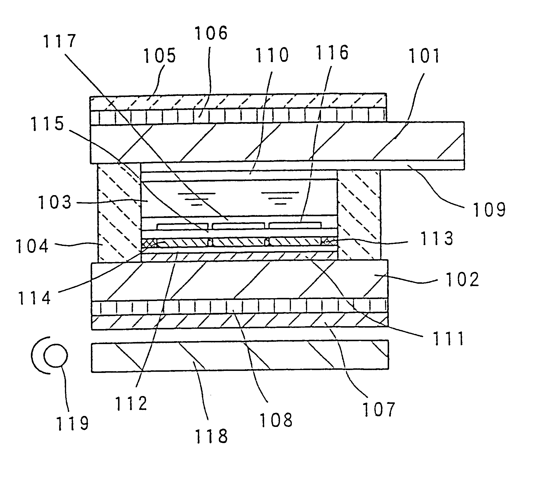
As shown in FIG. 1, in the first embodiment, there is formed between two transparent substrates 101 and 102 a liquid crystal cell in which a liquid crystal layer 103 is sealed in by a frame-like sealing material 104. The liquid crystal layer 103 consists of a nematic liquid crystal having a predetermined twist angle. On the inner surface of the upper transparent substrate 101, there are formed a plurality of stripe-like transparent electrodes 109 formed of ITO (indium tin oxide) layers or the like, and, on the surface of the transparent electrodes 109, there is formed an alignment layer 110, which has undergone rubbing processing in a predetermined direction.

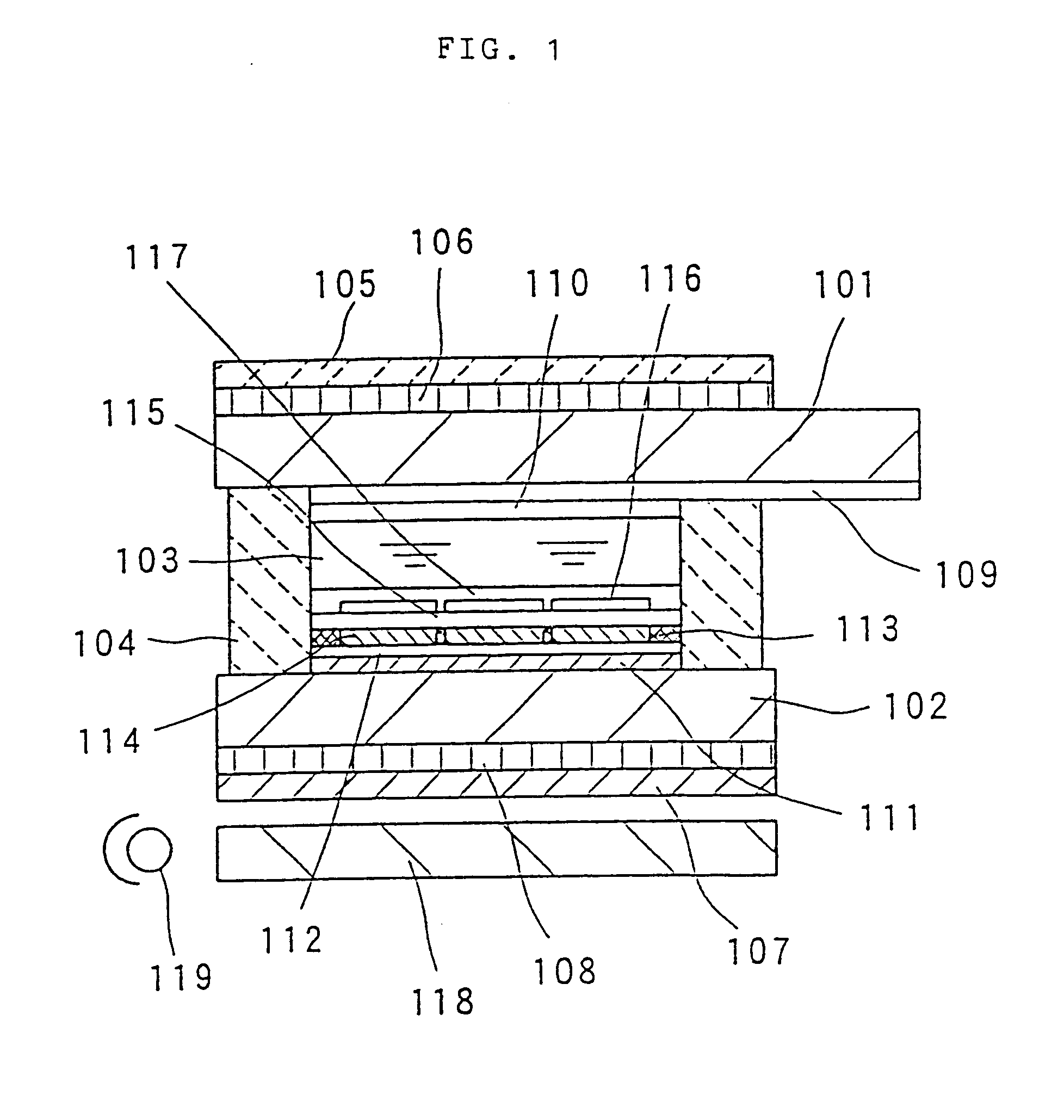
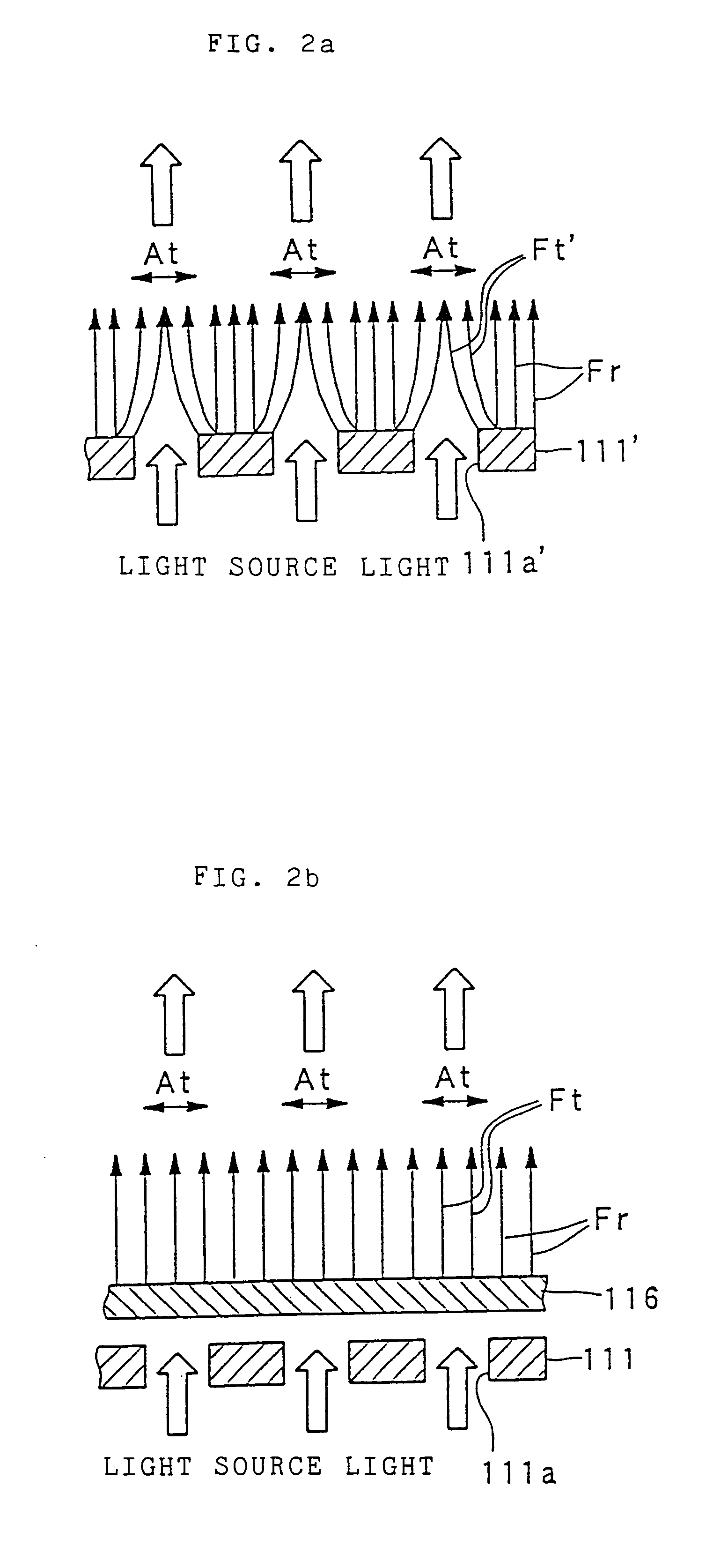
On the inner surface of the lower transparent substrate 102, there are sequentially formed a transflective plate 111, a protective layer 112 formed of SiO.sub.2, and a color filter 114. In the color filter 114, there are arranged in a predetermined pattern three color layers of R (red), G (green) and B (blue). The surface of the...

second embodiment

A second embodiment of the liquid crystal device of the present invention will be described with reference to FIGS. 5 and 6. FIG. 5 is a schematic longitudinal sectional view showing the construction of the second embodiment of the liquid crystal of the present invention. While this embodiment basically relates to a passive matrix type liquid crystal display device, a similar construction is also applicable to an active matrix type device, other segment type devices and other liquid crystal devices.

In this embodiment, a liquid crystal layer 403 is held between two transparent substrates 401 and 402 and sealed by a frame-like sealing material 404 to form a liquid crystal cell. The liquid crystal cell 403 is formed by a nematic liquid crystal whose dielectric anisotropy is negative. On the inner surface of the upper transparent substrate 401, there are formed a plurality of stripe-like transparent electrodes 409 consisting of ITO or the like; on the surface of the transparent electrod...

third embodiment

A third embodiment of the liquid crystal device of the present invention will be described with reference to FIGS. 7 through 10. FIG. 7 is a schematic longitudinal sectional view showing the construction of the third embodiment of the liquid crystal device of the present invention. While this embodiment basically relates to a passive matrix type liquid crystal device, a similar construction is also applicable to an active matrix type device, other segment type devices and other liquid crystal devices.

In this embodiment, a liquid crystal layer 203 is sealed between two transparent substrates 201 and 202 by a frame-like sealing material 204 to form a liquid crystal cell. The liquid crystal layer 203 is formed of a nematic liquid crystal having a predetermined twist angle. On the inner surface of the upper transparent substrate 201, there is formed a color filter 213, in which color layers of R (red), G (green) and B (blue) are arranged in a predetermined pattern. The surface of the co...


PUM

PropertyMeasurementUnit
thicknessaaaaaaaaaa
thicknessaaaaaaaaaa
wavelength rangeaaaaaaaaaa

Abstract

In a dark environment, when a backlight 119 is lighted, white light emitted from the surface of a light guide plate 118 passes through a polarizing plate 107 and a phase plate 108 and, further, passes through a transflective plate 111 and a transparent electrode 116 provided on the inner surface of a substrate 102 before it is introduced into a liquid crystal layer 3. Then, it is guided to the exterior of a liquid crystal cell and sequentially passes through a phase plate 106 and a polarizing plate 105 before it is guided to the exterior. In a bright environment, external light incident from the polarizing plate 105 passes through the liquid crystal layer 3, and is then reflected by the transflective plate 111 through the transparent electrode 116 before it is passed through the polarizing plate 105 again and guided to the exterior.

Description

The present invention relates to a liquid crystal device and, in particular, to a structure of a liquid crystal device capable of switching between reflection type display and transmission type display and to an electronic apparatus using this liquid crystal device.Conventionally, a reflection type liquid crystal device, which consumes little power, has been widely used as a display section attached to a portable device or apparatus. It has a problem in that it makes the display visible by utilizing external light, so that it is impossible to read the display in a dark place. In view of this, a liquid crystal device has been proposed which, in a light place, utilizes external light as a usual reflective type liquid crystal device but which, in a dark place, enables the display to be seen by means of an inner light source. As disclosed in Japanese Utility Model Laid-Open No. 57-049271, in this proposed device, a polarizing plate, a transflective plate, and a backlight are arranged in...

Claims


Application Information

Patent Timeline
Patent Type & Authority Patents(United States)
IPC IPC(8): G02F1/13G02F1/1335B65D51/00B60K15/04G02F1/13357G02F1/13363
CPCG02F1/133553G02F1/133555G02F1/13363G02F1/133615G02F2201/123G02F2203/09G02F2413/02G02F1/1335
Inventor MAEDA, TSUYOSHIOKUMURA, OSAMUOKAMOTO, EIJISEKI, TAKUMI
Owner 138 EAST LCD ADVANCEMENTS LTD
Why Eureka
Try Eureka