Fuel cell stack with separator of a laminate structure
Inactive Publication Date: 2004-02-10
PANASONIC CORP
View PDF12 Cites 37 Cited by
Summary
Abstract
Description
Claims
Application Information
AI Technical Summary
This helps you quickly interpret patents by identifying the three key elements:
Problems solved by technology
Method used
Benefits of technology
Benefits of technology
The object of the present invention is to provide a compact fuel cell stack that is manufactured by a simple process.
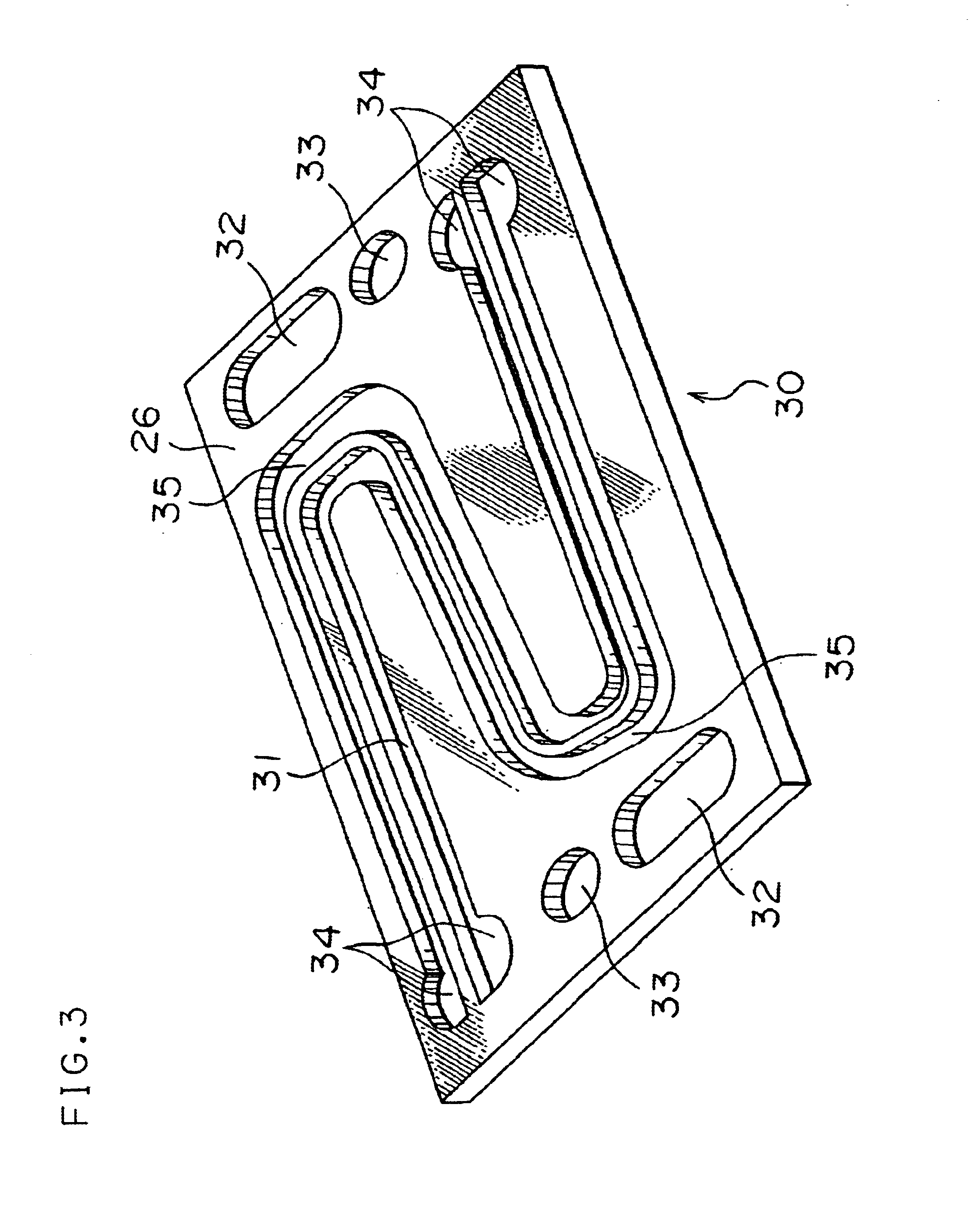
The slit has six bends 44 to improve the cooling ability in the example of FIG. 4, but the number of bends may be changed according to the requirements.
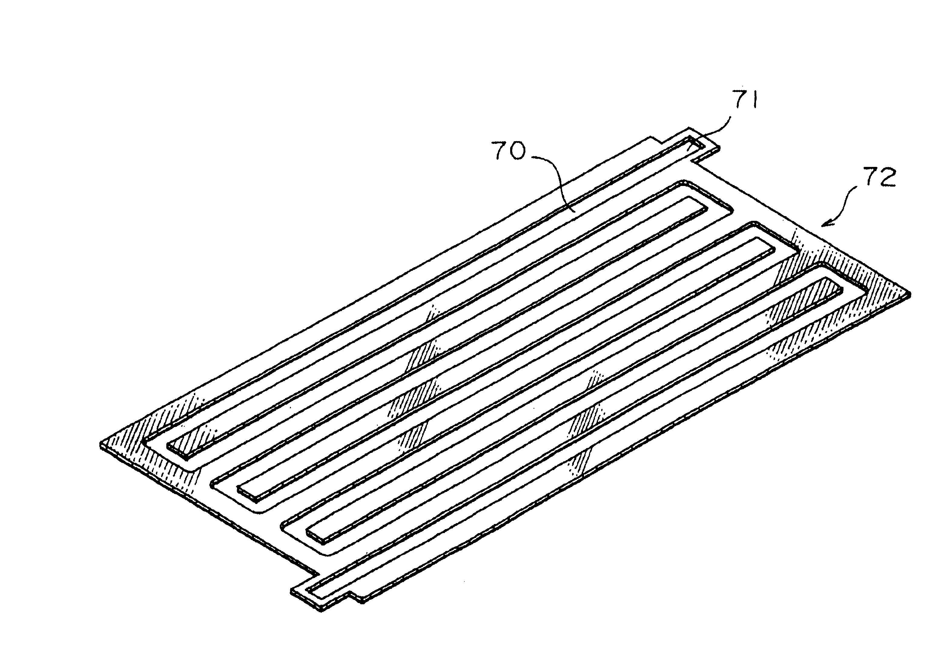
A conductive plate B 72 shown in FIG. 7 solves the problem of the conductive plate B shown in FIG. 6, that is, the separation of the conductive plate B into two members. A slit 70 has one end 71, which forms a lug 71 located outside the conductive plate B 72 and is not open to the outside. This arrangement prevents the conductive plate B from being separated into two members and facilitates the assembly of the fuel cell stack.
Problems solved by technology
This may cause the electrode to be poisoned with CO, which results in lowering the temperature and thereby further accelerating the poisoning of the electrode.
The cutting process, however, undesirably prevents mass production of the fuel cells with a low manufacturing cost.
The carbon plate typically has porosity and thereby relatively poor gas tight property.
The cured resin, however, hardly has elasticity, so that the carbon plate impregnated with the resin after the cutting process of the gas flow paths may have a warpage.
When a phenol resin or a silicone resin is used as the impregnating agent, the separator has insufficient acid resistance.
When a hard material like polytetrafluoroethylene is used for the separator, the molded separator does not have sufficient fluidity.
When the resin used as the impregnating agent has poor fluidity, it is required to decrease the content of the resin.
Method used
Image
Click on the blue label to locate the original text in one second.
Reading with bidirectional positioning of images and text.
Examples
example 2
In Example 2, the side faces of a fuel cell stack, which included 100 unit cells and was manufactured in the same manner as in Example 1, was sealed with a gas-tight rubber. The gas-tight rubber used here was a phenol resin. The phenol resin solution was spreaded on the side faces of the fuel cell stack and dried to seal the side faces of the fuel cell stack.
Evaluation
A battery test of the fuel cell stack thus obtained was carried out under the same conditions as those of Example 1. The output power of the fuel cell stack was 1080 W (30 A-36 V).
A leak test of this fuel cell stack was also carried out. In the test, an outlet of cooling water was closed and a hydraulic pressure was applied from an inlet of cooling water. No leakage of water was observed under the hydraulic pressure of 1 kgf / cm.sup.2. This proved the sufficient sealing property. From the result, it was confirmed that the arrangement of sealing the side faces of the fuel cell stack is extremely effective to improve the ...
example 3
In Example 3, an external manifold-type fuel cell stack was assembled as shown in FIG. 5 from the unit cells, which were manufactured in the same manner as in Example 1.
In first, specific parts corresponding to the internal manifolds were cut out from the unit cells manufactured in Example 1, and caused inlets and outlets of gases and cooling water to be exposed to the side faces of the unit cells.
A phenol resin used as the sealing rubber was spreaded on the side faces of the fuel cell stack and dried to seal the side faces of the fuel cell stack. In this example, the path of the inlets and outlets of gases and cooling water were not sealed by the sealing rubber. The phenol resin solution was carefully spreaded to make a flat sealing surface, which was in contact with the external manifold.
As shown in FIG. 5, the external manifolds 51 of stainless steel was arranged on the side faces of a unit cells 8 to cover an array of the exposed inlets of the air. In a similar manner, external ...
example 4
The process of Example 4 applied the conductive plate B shown in FIG. 6 for the separator having the flow paths of gas and cooling water and assembled an external manifold-type fuel cell stack by laying the unit cells manufactured in Example 3.
Evaluation
A battery test of the fuel cell stack thus obtained was carried out under the same conditions as those of Example 1. The output power of the cell stack was 1080 W (30 A-36 V).
The conductive plate B used for the separator has a through groove in the thickness of the conductive plate B. The through slit continuously meandering from one end to the other end of the conductive plate B favorably reduces the manufacturing cost.
PUM
Abstract
The present invention provides a fuel cell stack including a plurality of unit cells laid one upon another. Each of the unit cells includes an electrolyte, a pair of electrodes that are arranged across the electrolyte and respectively have a catalytic reaction layer, and a separator having means for feeding a supply of gaseous fuel to one of the electrodes and a supply of oxidant gas to the other of the electrodes. The separator is a laminate including a gas-tight conductive plate A and another conductive plate B having at least one slit, which continuously meanders from one end to another end of the conductive plate B. The technique of the present invention gives a compact fuel cell stack assembled by a simple process.
Description
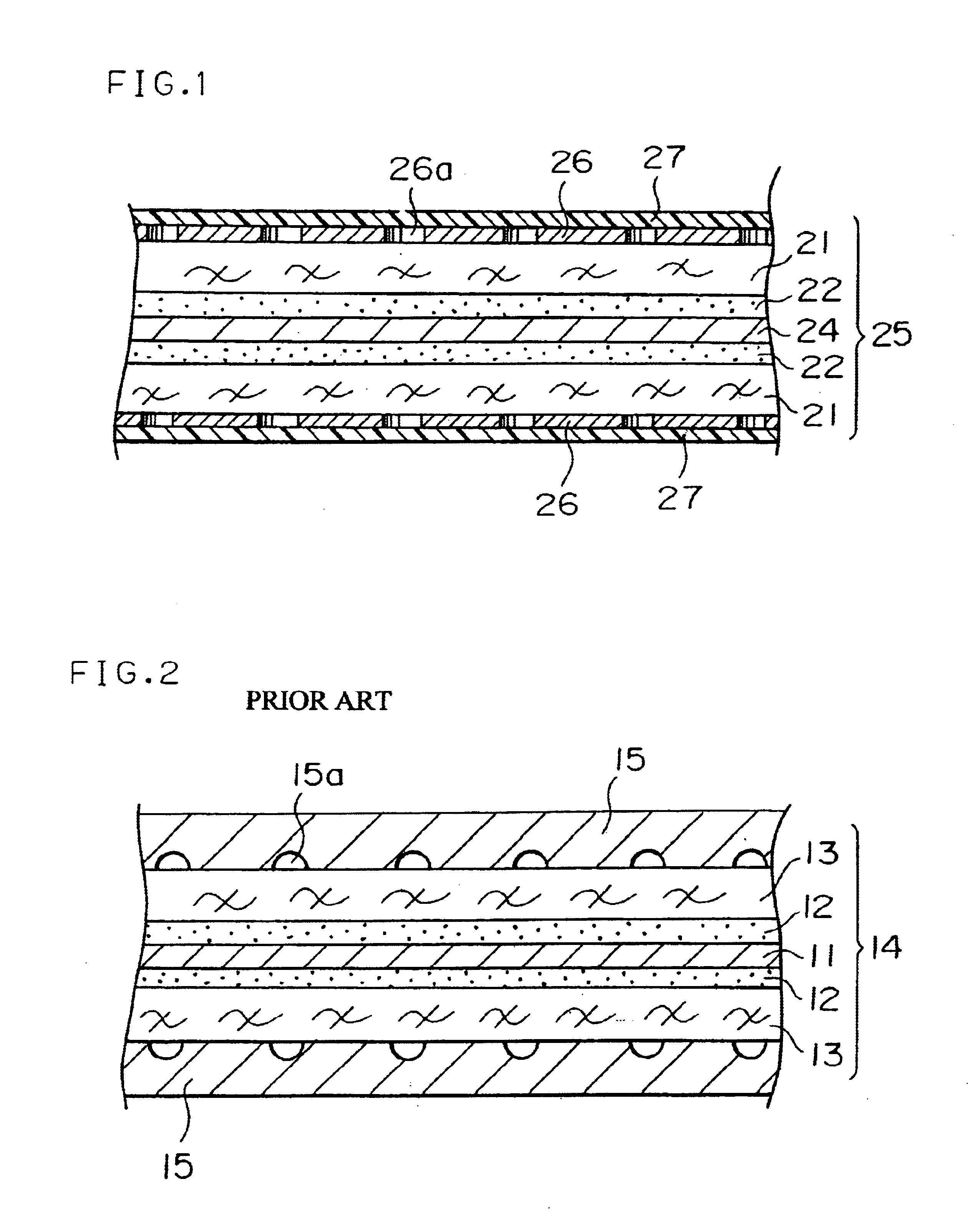
The present invention relates to a fuel cell, especially a polymerelectrolyte fuel cell, which is used for portable power sources, electric vehicle power sources, and domestic cogeneration systems.The fuel cells, especially the polymer electrolyte fuel cells, cause a fuel gas such as hydrogen, and an oxidant gas such as the air, to be subjected to electrochemical reactions at gas diffusion electrodes, thereby generating the electric power and the heat simultaneously.The structure of a conventional polymer electrolyte fuel cell is described below.FIG. 2 is a sectional view schematically illustrating a membrane electrode assembly (hereinafter referred to as MEA) in the conventional polymer electrolyte fuel cell. A pair of catalytic reaction layers 12, which are mainly composed of carbon powder with a platinum catalyst, are closely attached to both faces of a polymer electrolyte film 11. A pair of diffusionlayers 13 having both the gas permeability and the electrical conductivity are...
Claims
Application Information
Patent Timeline
Application Date:The date an application was filed.
Publication Date:The date a patent or application was officially published.
First Publication Date:The earliest publication date of a patent with the same application number.
Issue Date:Publication date of the patent grant document.
PCT Entry Date:The Entry date of PCT National Phase.
Estimated Expiry Date:The statutory expiry date of a patent right according to the Patent Law, and it is the longest term of protection that the patent right can achieve without the termination of the patent right due to other reasons(Term extension factor has been taken into account ).
Invalid Date:Actual expiry date is based on effective date or publication date of legal transaction data of invalid patent.

