Projection exposure apparatus, projection exposure method and catadioptric optical system

Inactive Publication Date: 2004-03-16
NIKON CORP
View PDF48 Cites 53 Cited by
  • Summary
  • Abstract
  • Description
  • Claims
  • Application Information

AI Technical Summary

Problems solved by technology

It is, however, difficult in terms of a geometry of the optical system that the numerical aperture NA of the projection optical system is set to a predetermined value or greater.
As a result, it is difficult to actualize a theoretically attainable resolution.
In the case of using this type of radiation source, however, the following problems arise.
First, there are an extremely limited kind of glasses that transmit beams having the wavelength of 180 nm or under.
Second, there are very few substances appropriate to be taken for an anti-reflection film, and hence it is difficult to form a preferable anti-reflection film.
Consequently, a radiation reflectance on each lens surface increases, with the

Method used


Image

  • Projection exposure apparatus, projection exposure method and catadioptric optical system
  • Projection exposure apparatus, projection exposure method and catadioptric optical system
  • Projection exposure apparatus, projection exposure method and catadioptric optical system

Examples


first embodiment and second embodiment

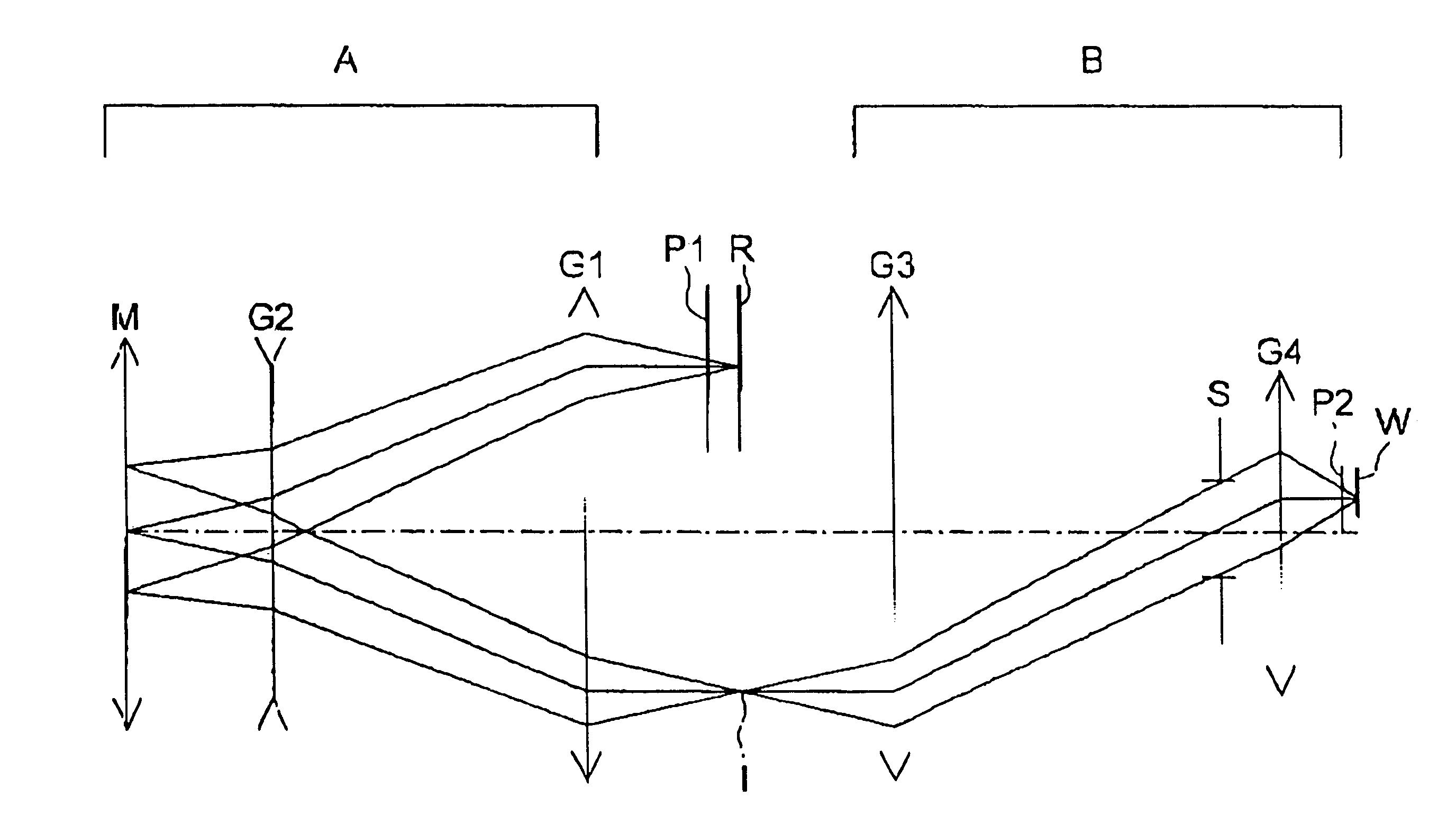
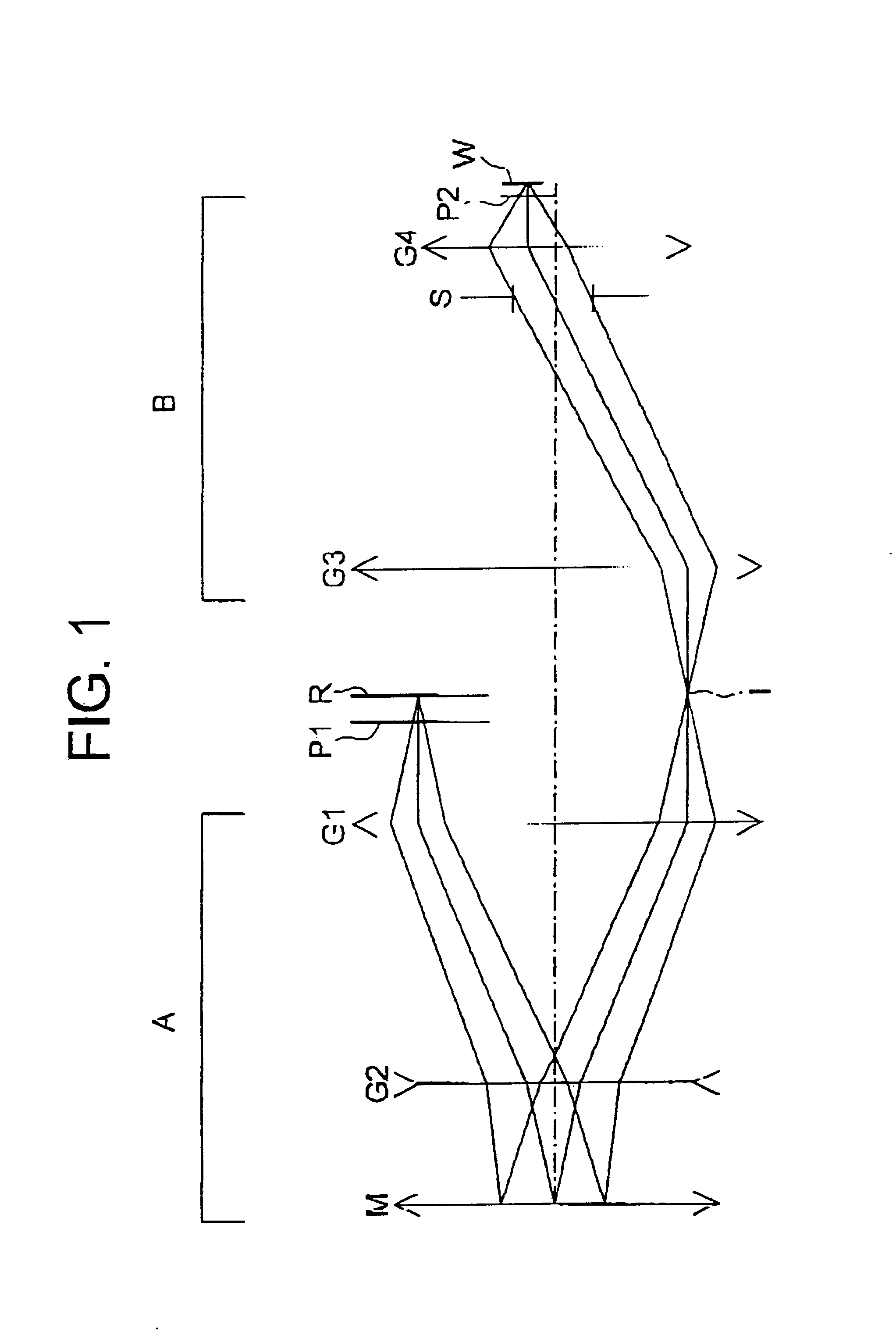
FIG. 3 is a view showing an outline of a whole construction of the projection exposure apparatus in first and second embodiments of the present invention. Incidentally, referring to FIG. 3, the Z-axis is set in a direction of normal line of the wafer surface, the X-axis is set in parallel to the sheet surface in FIG. 3, and the Y-axis is set perpendicularly to the sheet surface. Referring again in FIG. 3, the direction of gravity is the same as the direction of the Z-axis.

In the projection exposure apparatus illustrated therein, beams emitted in the Z-direction from the F.sub.2 laser 1 (of which an oscillation center wavelength is 157.6 nm), are deflected in the X-direction by a deflection mirror 2, and thereafter a mask 4 is uniformly illuminated with these deflected beams through an illumination optical system 3.

Note that only the single deflection mirror 2 is illustrated in the optical path from a radiation source 1 down to the illumination optical system 3 in FIG. 3, however, in...

first embodiment

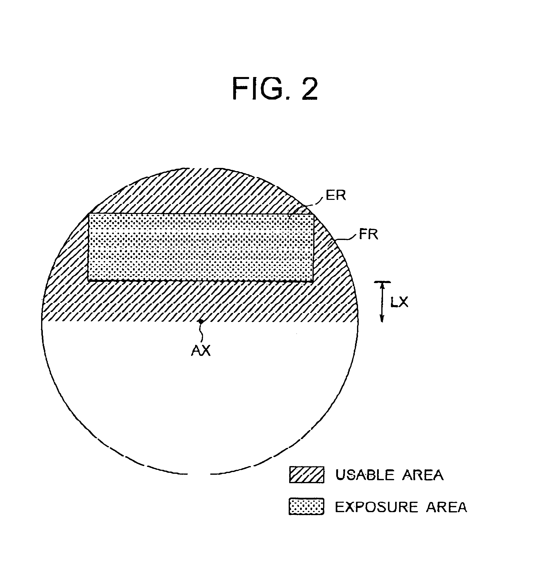
FIG. 4A shows a layout of the lenses of the projection optical system in a first embodiment, and is a sectional view taken along the plane perpendicular to the mask surface (object surface), including an optical axis connecting a concave reflecting mirror M2 to the wafer surface (image surface). Further, FIG. 4B corresponds to FIG. 4A and is a sectional view taken along the plane parallel to the mask surface, including the optical axis connecting the concave reflecting mirror M2 to the wafer surface (image surface). In FIG. 4B, however, for simplifying the illustration, the reflecting mirror M1 is omitted, and the optical paths from the reflecting mirror M1 to the mask R (corresponding to the reference numeral 4 in FIG. 3), are developed on the sheet surface. In the first embodiment, the present invention is applied to the projection optical system in which the variety aberrations containing the chromatic aberration are corrected with respect to the exposure radiation of which the c...

second embodiment

FIG. 7A shows a lens layout of the projection optical system in a second embodiment, and is a sectional view taken along the plane perpendicular to the mask surface (object surface), including the optical axis which connects the concave reflecting mirror M2 to the wafer surface (image surface). Further, FIG. 7B corresponds to FIG. 7A and is a sectional view taken along the plane parallel to the mask surface, including the optical axis connecting the concave reflecting mirror M2 to the wafer surface (image surface). Referring to FIG. 7A, however, for simplifying the illustration, the reflecting mirror M1 is omitted, and the optical paths extending from the reflecting mirror M1 down to the mask R are developed on the sheet surface. In the second embodiment, the present invention is applied to the projection optical system in which the various aberrations including the chromatic aberration are corrected for the exposure radiation of which the center wavelength is 157.6 nm and the full ...


PUM


Abstract

A projection exposure apparatus has an illumination optical system 3 for illuminating a mask formed with a pattern with beams of radiation, and a projection optical system for forming an image of the pattern on a workpiece on the basis of radiation from the mask. The illumination optical system supplies an illumination radiation having a center wavelength of 180 nm or smaller, and the projection optical system includes at least one concave mirror, fifteen or less pieces of refracting lenses, and four or more aspherical surfaces.

Description

1. Field of the InventionThe present invention relates to a projection exposure apparatus used in a lithography process in a line of manufacturing a semiconductor device, an imaging device such as a CCD etc, a liquid crystal display device, or a device such as a thin-film magnetic head etc. The present invention relates also to a catadioptric optical system used as a projection optical system of the this type of projection exposure apparatus. The present invention relates further to a projection exposure method using this type of projection exposure apparatus in the lithography process.2. Related Background ArtA reduction type projection exposure apparatus is widely used for manufacturing an integrated circuit such as an LSI. In the reduction type projection exposure apparatus, a reduced image of a mask pattern is formed on a wafer classified as a photosensitive substrate through the projection optical system. Over the recent years, a pattern of the integrated circuit, which is proj...

Claims


Application Information

Patent Timeline
IPC IPC(8): G02B17/08G03F7/20
CPCG02B17/08G02B17/0892G03F7/70225G03F7/70241G03F7/70358G03F7/70958
Inventor TAKAHASHI, TOMOWAKITSUKAMOTO, HIROYUKI
Owner NIKON CORP
Why Eureka
Try Eureka