
Electric contact and an electric connector both using resin solder and a method of connecting them to a printed circuit board

a technology of resin solder and electric connector, which is applied in the direction of connection contact member material, coupling device connection, sustainable manufacturing/processing, etc., can solve the problems of difficult or impossible to solder the electric contact onto the printed circuit board, and the inability to apply molten solder to the leg by an automatic machin

Inactive Publication Date: 2004-04-06
JST MFG CO LTD
View PDF48 Cites 69 Cited by
  • Summary
  • Abstract
  • Description
  • Claims
  • Application Information

AI Technical Summary

Benefits of technology

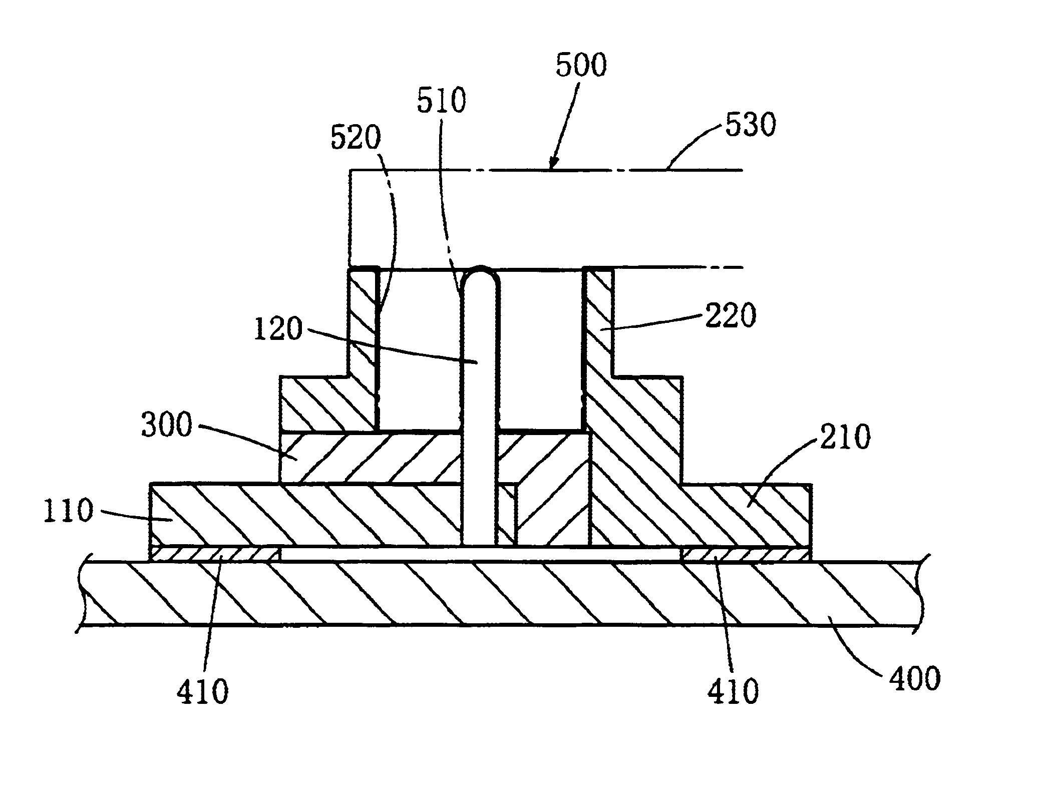
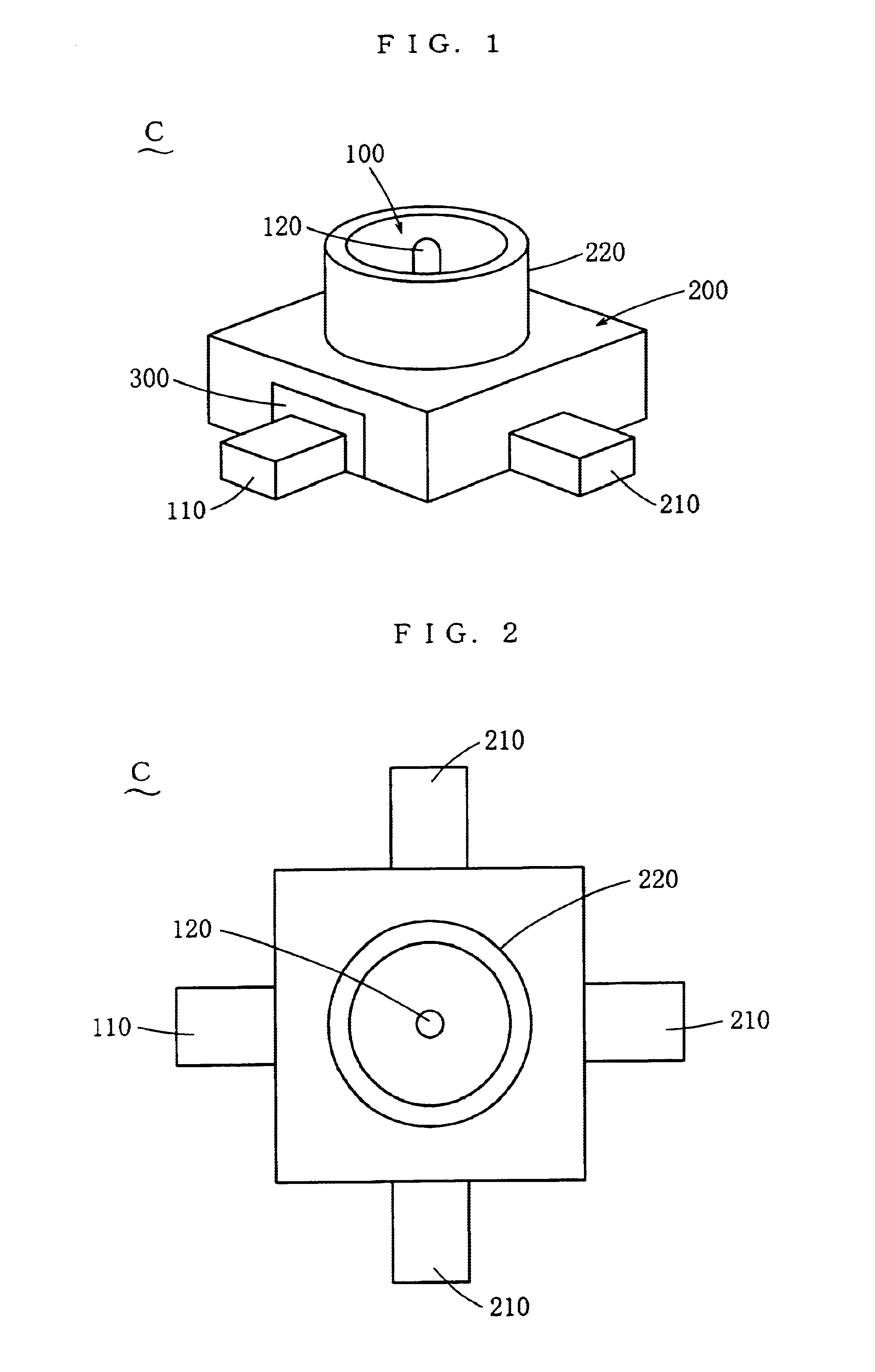
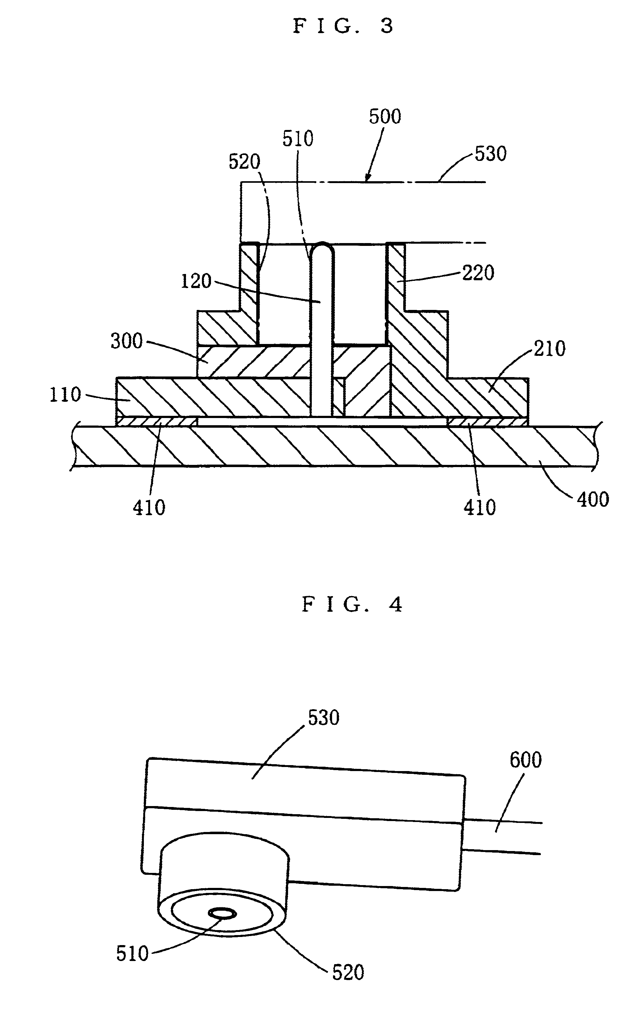
To accomplish the above-mentioned objective, an electric contact using resin solder according to the present invention is the electric contact, which is connected to a printed circuit board, which has a conductor being provided on a surface thereof, the electric contact comprises a leg, which contacts the conductor of the printed circuit board, and a connecting part, which is connected to a conductor of a counterpart member, and at least a part of the leg, which contacts the conductor of the printed circuit board, is made of a lead-free ultrahigh-conductive plastic being a conductive resin composite, comprising a thermoplastic resin, a lead-free solder that can be melted in the plasticated thermoplastic resin, and powder of a metal that assists fine dispersion of the lead-free solder in the thermoplastic resin or a mixture of the powder of the metal and short fibers of a metal.
When the leg of this electric contact is made to contact the conductor of the printed circuit board and the leg is heated, the lead-free solder being contained in the lead-free ultrahigh-conductive plastic of the leg will melt out and stick to the conductor of the printed circuit board. When the solder cools and solidifies, the electric contact will be mounted on the printed circuit board. Hence the work of separately applying solder is not required. Accordingly, even when it is difficult or impossible to solder the electric contact, for example, when another part is mounted too close to the electric contact, the electric contact can be mounted on the printed circuit board. Moreover, as solder quality control, temperature control and the like are not required, the control man-hour is reduced correspondingly. Further, even if the electric contact is microminiaturized, the mounting of the electric contact can be done easily by an automatic machine. Hence the productivity is increased and the cost is reduced. The lead-free ultrahigh-conductive plastic exhibits high conductivity, 10.sup.-3 .OMEGA..multidot.cm or under in volume resistivity. Hence the electric resistance of the electric contact can be lowered. Moreover, after the connection of the electric wire, when electricity is passed at a normal level, the lead-free ultrahigh-conductive plastic will not melt out due to heat generation. Further, in comparison with the technology of MID (Molded Interconnection Devices, for example, refer to Registered Utility Model gazette no. 2597015), wherein a conductive plated layer is formed on the surface of an insulator, the lead-free ultrahigh-conductive plastic provides the conductor with a larger cross-sectional area and a larger volume. Hence the resistance of the conductor can be reduced and the heat dissipation is better. This, in turn, allows passage of a larger current. Moreover, as the lead-free ultrahigh-conductive plastic can be molded by injection molding, it gives a greater freedom in molding. Hence it is easy to obtain impedance matching. When the electric contact is formed by injection molding, the accuracy of molding will be improved, and the connector using this electric contact will attain a higher coplanarity than an electric connector using an electric contact of sheet metal. Thus the risks of defective connection and short circuit are reduced. When only a part of the electric contact is made of the lead-free ultrahigh-conductive plastic and other parts are made of a material of which strength and elasticity are higher than those of the lead-free ultrahigh-conductive plastic, for example, a metal, the strength and the elasticity of the electric contact will be enhanced.

Problems solved by technology

However, it may be difficult or impossible to solder the electric contact if, for example, another part is mounted too close to the electric contact.
When the electric contact is held in an insulating housing to make an electric connector, the insulating housing may interfere and make it difficult to solder the electric contact onto a printed circuit board.
Further, if the electric contact is microminiaturized to connect with, for example, a very fine wire (for example, American Wire Gauge size 36 falls in the category of very fine wire, and the diameter of this electric wire is 0.12 mm approximately), the work of applying molten solder to the leg cannot be done by an automatic machine, and it is necessary to do the work manually by a skilled worker.
Hence the productivity is low, and this results in an increase in cost.
When such production processes are used, the legs of the electric contacts may set irregularly, making it difficult to obtain coplanarity.
This, in turn, is likely to lead to defective connection or short circuit.

Method used


Image

  • Electric contact and an electric connector both using resin solder and a method of connecting them to a printed circuit board
  • Electric contact and an electric connector both using resin solder and a method of connecting them to a printed circuit board
  • Electric contact and an electric connector both using resin solder and a method of connecting them to a printed circuit board

Examples


embodiment 1

45% by volume of ABS resin (produced by Toray; Toyolac 441), 40% by volume of lead-free solder (produced by Fukuda Kinzoku Hakufun Kogyo; Sn--Cu--Ni--AtW-150) and 15% by volume of copper powder (produced by Fukuda Kinzoku Hakufun Kogyo; FCC-SP-77, mean particle diameter 10 .mu.m) were lightly mixed together and fed into a kneader (Moriyama Seisakusho make, double-screw pressurized type) which was set at 220.degree. C. The mixture was kneaded, without preheating time, at a rate ranging from 25 to 50 r.p.m. for 20 minutes; the resin was heat-plasticated and the solder, under half-melted condition, was dispersed throughout the resin.

The kneaded material was pelletized by a plunger extrusion pelletizer (Toshin make, Model TP60-2) at the die temperature ranging from 200 to 240.degree. C. to produce pellets. These pellets were used to carry out injection molding into molds by an injection molding machine (Kawaguchi Tekko make, KS-10B). The preset temperature was from 230 to 280.degree. C....

embodiment 2

45% by volume of PBT resin (produced by Polyplastic), 40% by volume of lead-free solder (produced by Fukuda Kinzoku Hakufun Kogyo; Sn--Cu--Ni--AtW-150) and 15% by volume of copper powder (produced by Fukuda Kinzoku Hakufun Kogyo; FCC-SP-77, mean particle diameter 10 .mu.m) were lightly mixed together and fed into the kneader (Moriyama Seisakusho make, double-screw pressurized type) which was set at 220.degree. C. The mixture was kneaded, without preheating time, at a rate ranging from 25 to 50 r.p.m. for 20 minutes while efforts were made to prevent the temperature of the kneaded material from rising to 235.degree. C. or over, by lowering the rate of revolution, cooling, etc.; the resin was heat-plasticated and the solder, under half-melted condition, was dispersed throughout the resin. Observation, under an optical microscope, of the state of dispersion of the solder of the kneaded material showed that the solder was evenly dispersed throughout the resin and solder fractions were a...

embodiment 3

35% by volume of ABS resin (produced by Toray; Toyolac 441), 55% by volume of lead-free solder (produced by Fukuda Kinzoku Hakufun Kogyo; Sn--Cu--Ni--AtW-150) and 10% by volume of copper powder (produced by Fukuda Kinzoku Hakufun Kogyo; FCC-SP-77, mean particle diameter 10 .mu.m) were lightly mixed together, and the total of the metal components was set at 65% by volume. Then the mixture was fed into the kneader (Moriyama Seisakusho make, double-screw pressurized type) which was set at 220.degree. C. The mixture was kneaded, without preheating time, at a rate ranging from 25 to 50 r.p.m. for 20 minutes; the resin was heat-plasticated and the solder, under half-melted condition, was dispersed throughout the resin.

The kneaded material was pelletized by the plunger extrusion pelletizer (Toshin make, Model TP60-2) at the die temperature ranging from 200 to 240.degree. C. to produce pellets. These pellets were used to carry out injection molding into molds by the injection molding machin...


PUM

PropertyMeasurementUnit
diameteraaaaaaaaaa
volume resistivityaaaaaaaaaa
melting pointaaaaaaaaaa

Abstract

An electric contact using resin solder is connected to a printed circuit board, which has a conductor provided on a surface thereof. This electric contact comprises a leg, which contacts the conductor of the printed circuit board, and a connecting part, which is connected to the conductor of the counterpart member. At least a part of the leg, which contacts the conductor of the printed circuit board, is made of a lead-free ultrahigh-conductive plastic being a conductive resin composite. An electric connector includes the electric contact and an insulating housing, which holds the electric contact so that the part of the leg, which contacts the conductor of the printed circuit board, is exposed.

Description

1. Field of the InventionThe present invention belongs to a field of electric contacts and electric connectors, and relates to an electric contact and an electric connector, which are mounted on a printed circuit board by surface mounting.2. Related ArtAn electric contact is known, which is made of sheet of a metal such as copper alloy and comprises a leg, which contacts a conductor of a printed circuit board, and a connecting part, which is connected to the counterpart electric contact. This electric contact is surface-mounted on the printed circuit board by soldering the leg of the electric contact on the printed circuit board. An electric connector is also known, which comprises such an electric contact and an insulating housing, which holds the electric contact.When the above-mentioned conventional electric contact is to be mounted on a printed circuit board by soldering, molten solder will be applied to its leg. However, it may be difficult or impossible to solder the electric ...

Claims


Application Information

Patent Timeline
Patent Type & Authority Patents(United States)
IPC IPC(8): H01R13/00H01R13/03H01R13/646H05K3/34H05K13/04H01R4/02C08K3/08C08K7/06C08L101/12H01R4/68H01R12/57H01R13/46H01R24/50H01R43/24H05K1/03H05K3/32
CPCH01R12/57H01R13/03H01R24/50H05K3/3426H05K3/3442H05K13/0465H01R4/02H01R2103/00H05K2201/0129H05K2201/0215H05K2201/10909H05K2203/0425H05K2203/065H05K2203/1115Y02P70/50H01R4/68
Inventor HOSAKA, TAIJIMIYAZAWA, MASAAKI
Owner JST MFG CO LTD
Learn More